Deck 3500 Above Base – Part 2
Start situation – Deck 3500 Above Base - Part 2
- Set Visibility 'Distance in Front of View'
- Changing Plates - Part 1
- Changing Plates - Part 2
- Changing Plates - Part 3
- Create Arbitrary Profiles
You will switch to the lower deck "Deck 3500" to create the cutout in deck plate "Deck 3500".
Overview of actions:
- Open drawing top view "108-3500"
- Choose Update active block
- Make the bulkheads above the deck visible by increasing the "distance in front of view"
- Create the cutout in deck plate "Deck 3500"
- Modify the cutout by changing the parallel contour, related to the transverse bulkhead at FR29, in a slanted parallel contour
- Modify the cutout by relating the slanted parallel contour to the transverse bulkhead at FR28
- Create stiffener ST 150 x 10 along the slanted parallel contour of the cutout
- Undo the last plate modification
- Modify the cutout by changing the slanted contour back to a parallel contour
End situation – Deck 3500 Above Base - Part 2
Set Visibility 'Distance in Front of View'
As you can see on the drawing; the cutout in deck plate "Deck 3500" is related to its environment by means of parallel relations to the following three bulkheads:
- The longitudinal bulkhead at 6600 from CL;
- The transverse bulkhead at FR29;
- The longitudinal bulkhead at 3960 from CL.
But these bulkheads are not visible within the current top view "108-3500", because the visibility distance above the deck is too small. Normally within the CADMATIC Hull application only the plates below a deck will be shown. If you also want to see the bulkheads above the deck, you need to increase the visibility distance.
Please select the icon Drawing Properties:
![]()
Next you will be presented with the panel Drawing Properties:
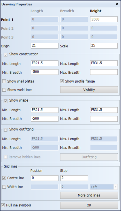
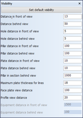
Click button Visibility to access the visibility settings within panel Visibility settings. Since the thickness of the deck is 12 mm, you have to change the value for Distance in front of view from 6 mm into at least 13 mm:
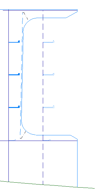
By clicking the OK button within panel "108-3500" the bulkheads will become visible in the top view.
Changing Plates - Part 1
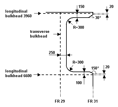
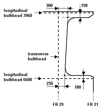
You will create the cutout in deck plate "Deck 3500" by modifying the contour of this deck plate. As mentioned before the cutout is related to its environment by means of the following three main relations:
- A parallel relation to the longitudinal bulkhead 6600 from CL of 100 mm;
- A parallel relation to the transverse bulkhead at FR29 of 250 mm;
- A parallel relation to the longitudinal bulkhead 3960 from CL of 150 mm.
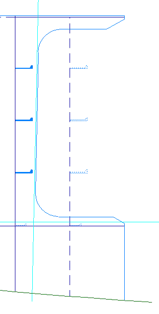
The dimensions of the cutout are presented in the figure below:
Please select the icon Change Plate Relations in the Modify section of the Plates tab:
![]()
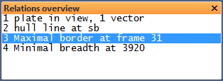
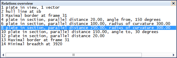
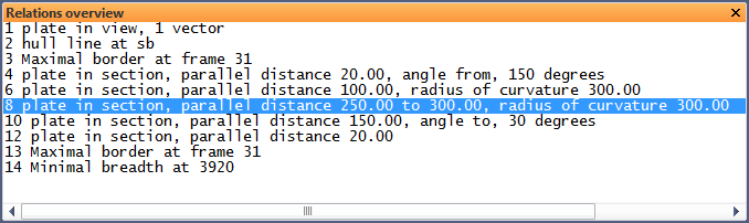
According to the hint Indicate construction part that has to be modified you select plate "Deck 3500". Next, the system displays a list of all the relations of the selected plate in the panel called Relations overview and you are also presented with the panel Modify a plate contour.
Now you have to indicate the relation which needs to be changed. Taking into account the rule that you should always work in a counterclockwise direction, you select the relation of the plate located at frame 31. This relation will be highlighted in panel Relations overview:
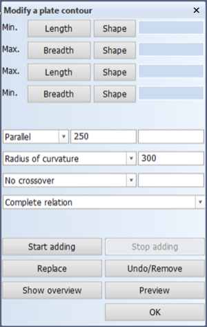
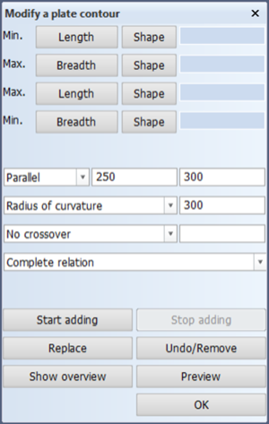
The selected relation properties are available within panel Modify a plate contour:
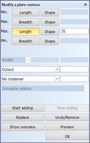
You will create the cutout in deck plate "Deck 3500" by starting at the indicated relation. Therefore you click the button Start adding to begin adding your modifications:
- The first part of the cutout is a small nose, starting at a parallel distance of 20 mm above the longitudinal bulkhead 6600. Start by indicating a point above the longitudinal bulkhead 6600 to select the deck and entering the value 20 for Parallel. Next, you define an angle of 150° by selecting option Angle from instead of No crossover and entering the value of 150, followed by <Enter>:

- The second relation is defined by a parallel distance of 100 mm from the longitudinal bulkhead 6600. Indicate the longitudinal bulkhead 6600 and enter the value 100 for Parallel;
- Add the lower corner radius of 300 mm by selecting Radius of curvature and entering the value 300;
- The third relation is defined by a parallel distance of 250 mm from the transverse bulkhead at FR29. So indicate the transverse bulkhead at FR29 at the front side and enter the value 250 for Parallel;
- Add the upper corner radius of 300 mm;
- The fourth relation is defined by a parallel distance of 150 mm from the longitudinal bulkhead 3960. Select the longitudinal bulkhead 3960 by indicating a point below it and enter the value 150 for Parallel;
- The last part of the cutout is also a small nose with a fixed angle of 30°, ending at a parallel distance of 20 mm below the longitudinal bulkhead 3960. Because the exact position of the start point is unknown, you cannot use the option Angle from. In such cases you use the alternative option Angle to. Select option Angle to and enter 30 as value for the angle:

Confirm this angle by pressing the <ENTER> key.
- The last action is to define the parallel distance of 20 mm below the longitudinal bulkhead 3960. Indicate the longitudinal bulkhead 3960 and enter the value 20 for Parallel.
Now click the button Stop adding and indicate the relation whereat the modification ends. In this case you select the relation of the plate located at frame 31.
You can get a preview of the modified deck plate by using the Preview button and the panel Relations overview will be updated:
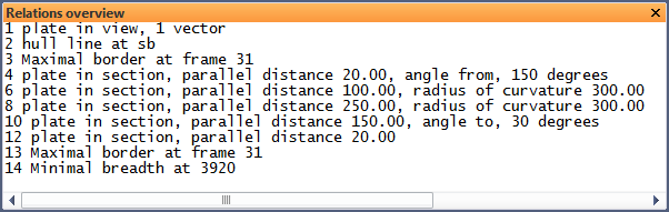
If you are satisfied with the result presented on your screen and in the panel Relations overview, then you can confirm the modification of the deck plate "Deck 3500" by clicking the OK button.
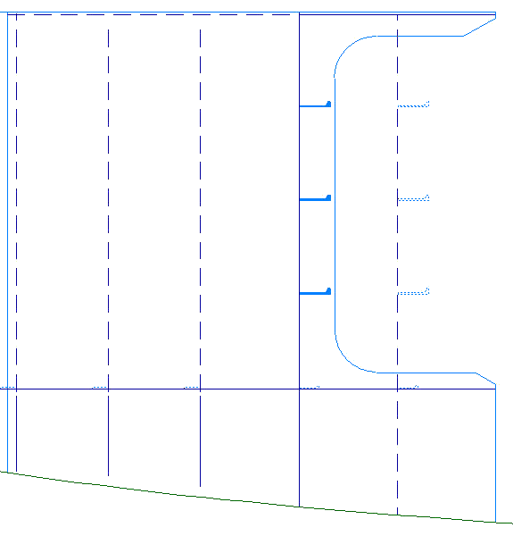
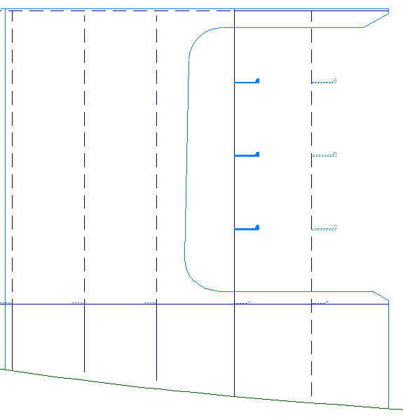
The end result is presented in the following figure:
Changing Plates - Part 2
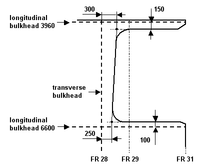
You will modify the created cutout in deck plate "Deck 3500" by changing the existing vertical plate boundary, which is related to the transverse bulkhead at FR29, in a slanted plate boundary.
Although this modification is not visible on the provided drawing sheets, you will carry out this modification as an additional exercise. The new dimensions of the cutout are given in the following figure:
Please select the icon Change Plate Relations in the Modify section of the Plates tab:
![]()
According to the hint Indicate construction part that has to be modified you select plate "Deck 6200". Next, the system displays a list of all the relations of the selected plate in the panel called Relations overview and you are also presented with the panel Modify a plate contour.
Now select the vertical plate boundary of the cutout, which is related to the transverse bulkhead. This relation is highlighted in panel Relations overview:
The selected relation properties are available within panel Modify a plate contour:
By specifying a second value for option Parallel, you define the current relation as a slanted relation with respect to the indicated plate in section.
The value in the left entry box for Parallel is the distance between the start point of the current relation and the selected item. The start point is determined by the intersection of the previous relation with the current relation.
The value in the right entry box is the distance between the end point of the current relation and the selected item. The end point is determined by the intersection of the next relation with the current relation.
Please notice that the current relation is seen as a straight line to determine the intersections.
Now insert the value 300 for Parallel in the right entry box as seen in this figure:

After clicking the OK button, the vertical plate boundary of the cutout will be modified into a slanted plate boundary.
The end result is presented in the figure below:

Changing Plates - Part 3
You will modify the created cutout in deck plate "Deck 3500" for a second time by making the cutout deeper. This can be realized by relating the slanted plate boundary of the cutout to the transverse bulkhead at FR28. Please notice that the slanted plate boundary of the cutout is currently related to the transverse bulkhead at FR29.
This second modification is an additional exercise to show you the use of the Replace button within panel Modify a plate contour. After carrying out this exercise, you will undo this modification.
The new dimensions of the cutout are illustrated in the following figure:
Please select the icon Change Plate Relations in the Modify section of the Plates tab:
![]()
According to the hint Indicate construction part that has to be modified you select plate "Deck 6200". Next, the system displays a list of all the relations of the selected plate in the panel called Relations overview and you are also presented with the panel Modify a plate contour.
Please select the slanted plate boundary of the cutout. The selected relation is highlighted in panel Relations overview:
The selected relation properties are available within panel Modify a plate contour:
You can replace an existing relation with a new relation by clicking the Replace button within panel Modify a plate contour.
In the current situation, you click the Replace button and define your new relation by indicating the transverse bulkhead at FR28. To see a preview of the modified deck plate, you click the Preview button. When you are satisfied with the result, you can click the OK button to confirm the modification of the deck plate "Deck 3500".
The end result is presented in the following figure:
Create Arbitrary Profiles
You will create stiffener ST 150 x 10 along the slanted plate boundary of the created cutout in deck plate "Deck 3500".
Although you will find the same profile on the sheet, there is one main difference: the presented profile on the sheet is a vertical profile, which can easily be created with the option Vertical Profiles.
To create this slanted profile, you will use the profile option called Arbitrary Profiles.
The stiffener ST 150 x 10 will be created between the start point P⊃1; and the endpoint P⊃2; along the slanted plate boundary. The exact position of these points are given in this figure:
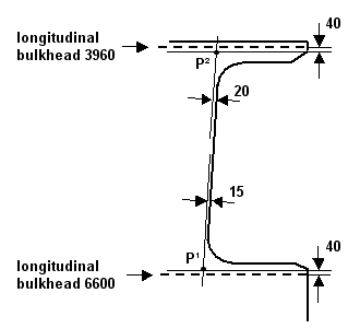
The start point P⊃1; will be defined as an intersection point between the following relations:
- A parallel relation to the longitudinal bulkhead 6600 from CL of 40 mm;
- A parallel relation to the slanted plate boundary of the cutout of 15 mm.
The end point P⊃2; will be defined as an intersection point between the following relations:
- A parallel relation to the longitudinal bulkhead 3960 from CL of 40 mm;
- A parallel relation to the slanted plate boundary of the cutout of 20 mm.
Both the first and second end shapes of this stiffener will be of type "B" with an angle of 60 mm and a nose height of 25 mm.
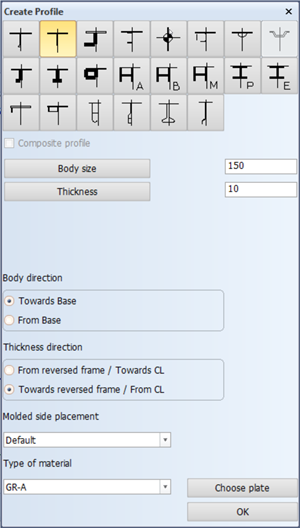
Please select on the Construction tab the icon Profiles, followed by the icon Arbitrary Profiles in the Insert section of the Profiles tab:
![]()
![]()
At first you have to specify the type of profile and its directions by means of panel Create profile. The profile type, body size and thickness are respectively 'Flat bar', 150 and 10. The profile directions will be Towards base and Towards reversed frame:
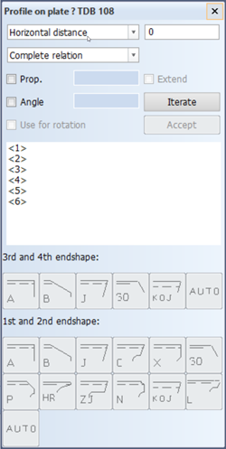
After clicking the OK button, you have to specify the start and end points of the profile and the corresponding end shapes by means of panel Profile on plate ? TDB 108:
As a base point for the start of the profile, you will define the following relations:
- A parallel relation to the longitudinal bulkhead 6600 from CL of 40 mm;
- A parallel relation to the slanted plate boundary of the cutout of 15 mm.
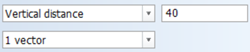
Ad 1. To define the first relation you select the longitudinal bulkhead 6600 by indicating a point above the plate and entering within panel Profile on plate ? TDB 108 the value 40 for Vertical distance:
Click the Accept button to confirm the definition of the relation. Please note that all the values concerning a relation should be given before you confirm it.
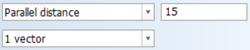
Ad 2. To define the second relation, you indicate the slanted plate boundary of the cutout, but when you select this plate, the full contour of the plate will be highlighted! You will see this in panel Profile on plate ? TDB 108 as well, where the selected type of relation will be Complete relation:
To make sure that only the indicated slanted plate boundary is selected, you have to choose 1 vector as the type of relation from the drop-down menu. Generally speaking the selected type of relation 1 vector means that only the vector of the relation, which is closest to the indicated point will be selected.
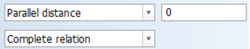
Now enter the value 15 for Parallel distance:
Confirm the definition of this relation by clicking the Accept button.
You have defined two relations which are presented in the graphical screen as two additional lines intersecting each other:
The intersection point of these two lines will determine the start point of the profile.
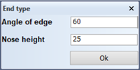
According to the hint, you have to choose the third and first end shape in panel Profile on plate ? TDB 108. Since the profile does not have a flange, you only have to define the first end shape, which will be of type 'B' or a so-called "snipe":
![]()
Please accept the presented default values for Angle of edge and Nose height within panel End type by clicking the OK button:
As base point for the end of the profile, you will define the following relations:
- A parallel relation to the longitudinal bulkhead 3960 from CL of 40 mm;
- A parallel relation to the slanted plate boundary of the cutout of 20 mm.
Ad 3. To define the third relation you select the longitudinal bulkhead 3960 by indicating a point below the plate. Next you enter the value 40 for Vertical distance. Confirm the definition for this relation by clicking the Accept button.
Ad 4. You define the fourth relation by selecting the slanted plate boundary of the cutout and choosing 1 vector from the drop-down menu for the correct type of relation. Enter the value 20 for Parallel distance and confirm by clicking the Accept button.
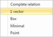
An alternative for selecting the type of relation 1 vector from the drop-down menu is by using the right-mouse button after selecting the slanted plate boundary. The following pop-up menu appears, which enables you to select the appropriate type of relation:
The defined relations will be presented as additional lines in the graphical screen. The intersection point of these two lines will determine the endpoint of the profile.
According to the hint, you have to choose the fourth and second end shape in panel Profile on plate ? TDB 108. You only have to select the second end shape, which will be of type 'B'. Accept the presented default values for Angle of edge and Nose height within panel End type by clicking the OK button.
The stiffener ST 150 x 10 will be created between the specified start and end points: