Frames 24-30
You will switch to frame view "Frame 24" to make sure that the attributes of the upper plate "Bulkhead Fr. 23" are indeed available. To finish the upper plate "Bulkhead Fr. 24" you will add the welding holes with radius 35 mm.
Overview of actions:
- Open drawing frame view "108-24"
- Choose Update active block and you will notice that the plate and its attributes are there
- Create two welding holes with radius 35 mm
- Open drawing frame view "108-25"
- Modify the size of the current hole of the upper plate "Bulkhead Fr. 25" from 1200/450 mm into 800/450 mm and shift it 250 mm in height
- Copy this hole -1200 mm in height and -100 mm in breadth
- Copy the upper plate "Bulkhead Fr. 25" and all its attributes to the frames 26 and 27
- Create two welding holes with radius 35 mm
- Open drawing frame view "108-26"
- Create extended cutout for upper plate "Bulkhead Fr. 26"
- Create a welding hole with radius 35 mm
- Open drawing frame view "108-27"
- Shift the hole of the upper plate "Bulkhead Fr. 27" at height 4300, 100 mm in breadth
- Copy the upper plate "Bulkhead Fr. 27" and all its attributes to the frames 28 and 30
- Create extended cutout for upper plate "Bulkhead Fr. 27"
- Create a welding hole with radius 35 mm
- Open drawing frame view "108-28"
- Create a welding hole with radius 35 mm
- Open drawing frame view "108-30"
- Create a welding hole with radius 35 mm
- Shorten the profile HP120x8 of the upper plate "Bulkhead Fr. 30" at the lower end to the Deck 3500 with a distance of 40 mm
Modify Plate Relation
Due to the fact that at Frame 26, the corner hole and the hole at the seam are getting too close to each other, you are going to create one extended hole to meet the same purpose. This extended hole will need to be added to the plate contour, which is what you are going to do in this step.
Before you begin, there are a few values you need to obtain. You will be needing these values when creating the actual cutout. These values are:
- The height of the soon to be created cutout at Frame 26
- The angle of the hull line at Frame 26
When you zoom in on, and then select the concerning seam, you will notice that the seam symbol has a node point which intersects with the hull line. You can use this point as the centre point of a temporary circle. This temporary circle will help to determine the height of the cutout.
Let's create a circle by selecting on the Draw tab the arrow under icon Circles in the Insert section, and choose Centre, Radius:
![]()
![]()
Alternatively, you can also directly click on the icon Circles, which starts the first function in the list.
Now proceed to snap to the node point of the seam symbol by using hot key <n>. Enter for the radius of the circle the value 50. Exit the circle function by means of the <Esc> key, and place the current control at the upper intersection point between the circle and the hull line by means of the hot key <i>.
Now, when you look at the current control coordinates, you see that the displayed minimum height is approximately 3650. You will need this value later on.
For the relation perpendicular to the hull line, you will need to find out the angle of the hull line by retrieving information about it.
Let's retrieve the angle of the hull line by selecting the icon Line/Arc Information in the Information section of the Draw tab:
![]()
According to the hint Indicate a line you select the hull line at the point where it intersects with the circle you have drawn. Now the system displays the panel Line Information:

As you can see, the angle of the hull line is 59.36, which can be rounded off to 59°.
Now we have enough information to start editing the plate to create the cutout.
Indicate the plate in the graphical screen to open the Plates ribbon tab. Select Change Plate Relations in the Modify section:
![]()
According to the hint Indicate construction part that has to be modified you select plate "Bulkhead Fr. 26". After selection, the system will display panel Relations overview with the current plate boundaries:
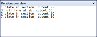
Taking into account that plate relations are always counterclockwise, you will need to add the new relations pertaining to the cutout that you're about to create, in between relations 1 and 3. You do this by means of panel Modify a plate contour:

Select relation 1 and remember to remove the value '75' that is still defined for the cutout. Now click the button Start adding to begin adding the cutout to the plate.
- The first relation of the cutout runs parallel to the hull line. Select the hull line by indicating a point on the left-hand side of it and directly after, enter the value 50 for Parallel in the panel Modify a plate contour;
- Now add the corner radius of 50 mm to this relation by selecting option Radius of curvature and entering the value 50 in the entry box;
- When you follow the contour of the circle, which represents the path of the cutout, you see that where the arc you just defined starts, the line bends off and lands exactly perpendicular to the hull line. In order to establish this for the cutout, you need to select Angle to and define the angle of the hull line minus 90°. Enter 59-90 in the entry box and press <Enter> to confirm the angle;
- The last boundary of the modification is defined by the minimum height. Select the Min. Height button and enter value 3650 in the entry box.
Note: The value for the angle must always be confirmed by pressing the <ENTER> key.
Now you have defined all the necessary relations to create the cutout, and you need to click the button Stop adding.
Before you clicked Start Adding, you indicated the relation that contained the cutout you removed. Taking into account the counter-clockwise rule, this is the relation where you started your modification. Now you have to indicate the relation whereat the modification ends as well.
Indicating these two relations before you start your modification and when you end it, is necessary to determine where on the plate the modification takes place. Therefore these are always existing relations of the plate. In this situation you select the hull line.
Please click the Preview button to see a preview of the modified plate. The updated plate relations appear within panel Relations overview:
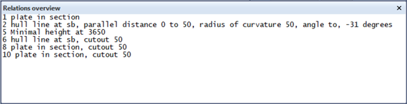
Please click the OK button to finalize your modification, and see the cutout appear in the plate.