Frame 24
You will switch to frame view "Frame 24" to complete the floor "Bulkhead Fr. 24" between the hull and the lower deck "Deck 3500".
This floor has been copied from frame 23 with its three stiffeners ST 100 x 10 and two holes with diameter 450 mm. You will make the following necessary modifications to this floor:
- Change the position of the holes with diameter 450 mm from 3100 into 3000 mm above base;
- Change the left lower corner radius from 100 into 75 mm, which is how the plate contour was defined;
- Add two welding holes with radius 35 mm and one welding hole with radius 75 mm.
Overview of actions:
- Open drawing frame view "108-24"
- Choose Update active block
- Place standard text "Frame 24" above view using current control
- Change left lower corner radius from 100 to 75 mm
- Change position of holes with diameter 450 mm from 3100 to 3000 mm above base
- Create two welding holes with radius 35 mm and one welding hole with radius 75 mm
- Copy floor 24 to 25 without attributes and see the preview in Hull Viewer
- Copy the attributes on floor 24 to floor 25 and see the preview in Hull Viewer
Additional description of actions:
- Place standard text "Frame 24" above view
Placing standard text "Frame 24" above view is similar to placing standard text "Frame 23" above view, but now you select as standard text "Frame 24".
- Change position of holes with diameter 450 mm from 3100 to 3000 mm above base
The position of the holes with diameter 450 mm can be changed by shifting them -100 mm in height. Shifting these holes is similar to shifting the aft most hole from Deck 6200, but now you select on panel Hole selection menu the option Shift in height and enter the value -100. Instead of using that value, you can also use the absolute value for the height by selecting the Abs option and entering the absolute height.
- Create two welding holes with radius 35 mm and one welding hole with radius 75 mm
The creation of two welding holes with radius 35 mm and one welding hole with radius 75 mm is similar to the creation of welding holes within frame view "Frame 23".
- Copy floor 24 to 25 without attributes and see the preview in Hull Viewer
|
Name of panel |
Option |
Value |
|---|---|---|
|
Copy items |
'Selection method' |
Cross hair |
|
|
'Selection treatment' |
Select |
|
|
|
Select the floor by indicating a point near the hull line |
|
|
|
Uncheck 'Include attributes' |
|
Copy items |
|
Click button 'Shift' |
|
Copy items |
Tab; 'Shift'->'Shift actions' |
|
|
|
'Length' |
1 |
|
|
'Amount' |
1 |
|
|
'Step' |
1 |
By clicking the OK button, the floor will be copied to frame view "Frame 25".
- Copy the attributes on floor 24 to floor 25 and see the preview in Hull Viewer
|
Name of panel |
Option |
Value |
|---|---|---|
|
Copy items |
'Selection method' |
Conflict |
|
|
'Selection treatment' |
Select |
|
|
|
Drag the selection box across the holes and the stiffeners in one action |
|
|
|
'Include attributes' |
|
Copy items |
|
Click button 'Shift' |
|
Copy items |
Tab; 'Shift'->'Shift actions' |
|
|
|
'Length' |
1 |
|
|
'Amount' |
1 |
|
|
'Step' |
1 |
By clicking the OK button, the attributes on floor 24 will be copied onto the floor at frame view "Frame 25".
Modify Plate Relation
The plate "Bulkhead Fr. 24" between the hull and the lower deck "Deck 3500" contains at the lower left corner a corner hole with a radius of 100 mm. This corner hole is part of the plate contour. You will change the radius of this corner hole into 75 mm by modifying the plate.
Select the icon Change Plate Relations in the Modify section of the Plates tab:
![]()
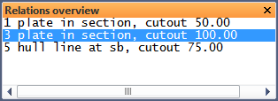
According to the hint Indicate construction part that has to be modified you select the floor. After selecting the floor, the system will display the panel Relations overview with the current plate boundaries, as well as the panel Modify a plate contour with the plate contour definitions.
According to the hint Indicate relation to be changed you indicate the lower left corner on the graphical screen. The relation will be highlighted within the Relations overview panel:
The selected relation properties are available within panel Modify a plate contour:

You change the radius of the corner hole by changing value "100" into 75 for Cutout:

By clicking the OK button, the radius of the corner hole will be changed from 100 into 75 mm.