Frame 27
You will switch to frame view "Frame 27" to modify the floor between the hull and the lower deck "Deck 3500". You will make the following modifications to this floor:
- Change the position of all holes from 3000 into 2800 mm above base;
- Change the type and size of the outmost hole from type "manhole" with diameter 450 mm into type "creep hole" with height 600 mm and breadth 450 mm;
- Change the upper right corner radius from 75 to 100 mm;
- Add three welding holes with radius 35 mm around the seams in the hull;
- Change the radius of the inner welding hole from 35 to 75 mm.
When you have completed these modifications, you will copy the floor to frame 28 and frame 30. Please remind that welding holes are not topological and therefore the best procedure is to copy the floor first and then create the welding holes.
Overview of actions:
- Open drawing frame view "108-27"
- Choose Update active block
- Place standard text "Frame 27" above view using current control
- Change position of all holes from 3000 to 2800 mm above base
- Modify the type and size of the outmost hole into creep hole 600/450 mm
- Change upper right corner radius from 75 to 100 mm
- Copy floor to frame 28 and frame 30
- Create three welding holes with radius 35 mm
- Change radius of inner welding hole from 35 to 75 mm
Additional description of actions:
- Copy floor to frame 28 and frame 30
You will create the floors at frame 28 and 30 by copying the modified floor "Bulkhead Fr. 27" from frame 27.
|
Name of panel |
Option |
Value |
|---|---|---|
|
Copy items |
'Selection method' |
Cross hair |
|
|
'Selection treatment' |
Select |
|
|
|
Indicate the floor |
|
|
|
'Include attributes' |
|
Copy items |
|
Click button 'Shift' |
|
Copy items |
Tab; 'Shift'->'Shift actions' |
|
|
|
'Length' |
1 |
|
|
'Amount' |
2 |
|
|
'Step' |
2 |
By clicking the OK button, the floor will be copied to frame views "Frame 28" and "Frame 30".
Change Radius of Welding Hole
The floor between the hull and the lower deck "Deck 3500" contains three welding holes with a radius of 35 mm. But according to the sheet, the radius of the inner welding hole has to be changed from 35 into 75 mm.
Let's change the radius of the inner welding hole by selecting on the Construction tab the icon Draining/Corner Holes:
![]()
The ribbon tab Draining/Corner Holes is opened:

The Modify section contains three modification options for corner holes:
- Size User-Holes
![]()
- Size Air Holes
![]()
- Shift
![]()
In this case the radius of the inner welding hole must be changed by selecting the icon Size User-Holes:
![]()
By means of panel Corner Hole Selection Menu, you select, according to the hint Select a corner hole, the inner welding hole by using the 'Clump' selection method:
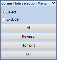
After selecting the inner welding hole, you click the OK button and you will be presented with the panel Corner holes to determine the type of corner hole:
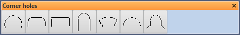
Please select "type 348":
![]()
You enter the new corner hole radius by means of panel Hole types:
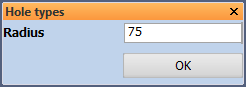
Click the OK button and the radius of the inner welding hole will be changed into 75 mm.