Frame 30 – Part 2
Start situation – Frame 30 - Part 2
You will add the flange with flange size 100 mm to the floor "Bulkhead Fr. 30", located between the hull and the lower deck "Deck 3500". There will also be three brackets added to this view.
Overview of actions:
- Open drawing frame view "108-30"
- Choose Update active block: the upper boundary of the floor is partly missing
- Check if the floor is really present
- Add the missing upper line to the floor
- Add flange with size 100 mm to the floor
- Create bracket "G 33" between deck beam HP 140 x 8 and longitudinal bulkhead 3960
- Create bracket "B 10" between deck beam HP 140 x 8 and profile HP 200 x 9
- Create bracket "A 04" between profile HP 200 x 9 and the flange of the floor
- Update all views
End situation – Frame 30 - Part 2
Additional description of actions:
- Check if the floor is really available
You can check if the floor is really present by activating the background lines. You will see that the floor is there, but the upper line is missing. Within CADMATIC Hull all relations belonging to plates in view that are related to other plates are not shown. This to prevent having multiple lines end up on top of each other.
This floor is originally related to the lower deck and so therefore this relation is not presented as a line. But in this case a part of the deck has been removed due to the cutout you created earlier. However, the system does not automatically detect this. In such cases it's possible to add a line later on.
- Update all views
Updating all of the views is similar to recalculating all views at the basic training step 33.
Create Visible Lines
Now you will add the missing upper line to floor "Bulkhead Fr. 30":
Add a line to the existing floor by selecting the icon Plate Contour in the Presentation section of the Plates ribbon tab:
![]()
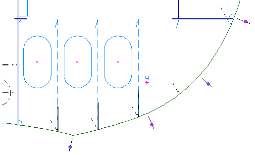
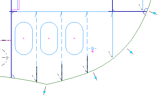
According to the hint Select plate in view you select the floor and the contour direction of this floor will be shown by means of arrows:
Now let's define the start and end point of the new line and its dash type by means of panel Plate Contour:
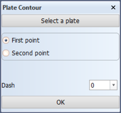
You define the first point, where the line should start, by indicating the upper boundary of the plate near the longitudinal bulkhead 6600. But the actual start point P1 will be the intersection point of the upper boundary and the hull line.
Next, you define the second point, where the line should end, by selecting option Second point on panel Border value, and indicating the upper boundary near longitudinal bulkhead 3960. The end point P2 will be the intersection point of the upper boundary and the longitudinal bulkhead 3960.
You will want to create a solid line, meaning that the corresponding dash type Dash will be '0'.
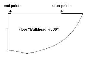
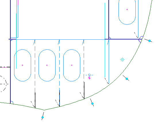
Both points of the new line are illustrated in the figure below:
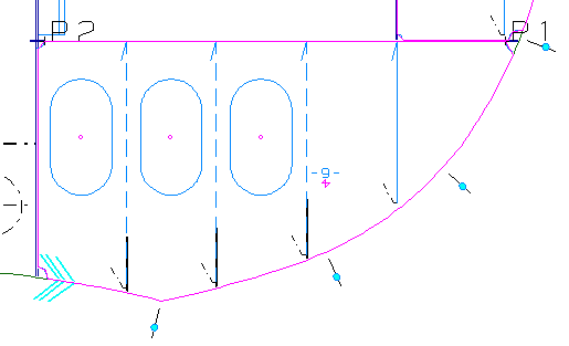
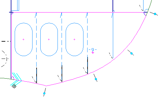
After clicking the OK button, the new line will appear over the upper edge of the plate:
By closing the panel you can leave the function.
Create Flanges
You will create a flange of 100 mm and add it to the upper edge of the plate "Bulkhead Fr. 30". As opposed to the flange of the longitudinal girder "Long. bulkhead 3960", this flange will not cover the full length of the upper plate boundary but only a part of it!
Select on the Construction tab the icon Flanges, followed by the icon Flange in the Insert section of the Flanges tab:
![]()
![]()
According to the hint Indicate the side of the plate where the flange/face plate should be placed you indicate a point just above the upper boundary of floor "Bulkhead Fr. 30".
First you define the size of the flange and the direction by means of panel Face plate on plate 29 TDB 108:
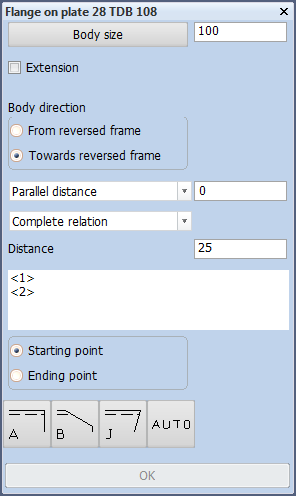
The body size is 100 mm and the body direction will be towards reversed frame.
Secondly you specify the start and end point of the flange, taking into account the contour direction of the plate to which the flange will be attached:
The start point will be located to the left of the visible part of the deck plate at the right hand side, and can be defined by indicating a point at this end. To make sure you select the correct plate to establish the relation for the flange here, right-click the mouse anywhere to open the following menu:
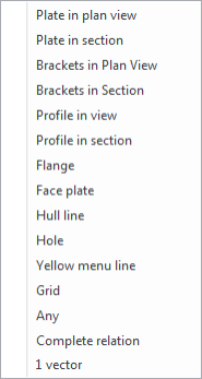
When you select Plate in section, lower deck "Deck 3500" will light up, which is exactly the plate you need to relate the flange to.
Accept the default value "25" for the distance from the start point and select for the end shape type 'B':
![]()
You accept the default values for angle and nose height within panel "End type" by clicking the OK button.
The end point will be located to the right side of the visible part of the deck plate at the right hand side and can be defined by indicating a point at this end. Use the same method as above to indicate lower deck "Deck 3500" to relate the flange to.
You specify the same distance of "25" and the same end shape, meaning type 'B' with its default properties for the end point. By clicking the OK button within panel End type you have also defined the end point of the flange.
Now both ends of the flange are defined. Two additional lines have appeared to emphasize the start and end points of the flange:
Next you click the OK button to create the flange on the floor "Bulkhead Fr. 30".
You can check if the flange has really been added to floor "Bulkhead Fr. 30" by coding this floor.
First you select the Code One Part icon on the Production tab:
![]()
Secondly you indicate floor "Bulkhead Fr. 30". The coded part should look like this:
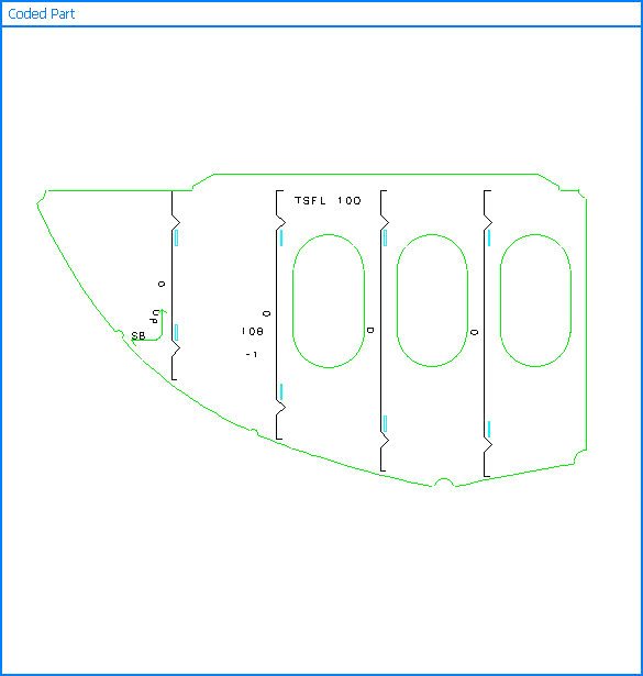
Please notice that coded parts are presented upside down by default.