Longitudinal Slanted Plate and Knuckles
Start situation – Longitudinal Slanted Plate and Knuckles
Now we will switch back to proceed working in block 108.
In this step you will create three new views, of which two regular side views and one perpendicular side view. In each side view you will create a new plate and then you will connect these plates together with use of the knuckle attribute.
After this you will proceed to bring these three separate views together to create one drawing.
In this step you will also create holes using the related holes function.
Overview of actions:
- Create side view 4620
- Edit the standard text to "4620 off C.L."
- Save the drawing with the name "4620-knuckle"
- Remove all profiles and brackets in this view
- Create plate 4620 with a thickness of 9 mm
- Create related holes
- Create side view 5280
- Edit the standard text to "5280 off C.L."
- Save the drawing with the name "5280-knuckle"
- Remove the profile on the far left
- Create plate 5280 with a thickness of 9 mm
- Create slanted view
- Save the drawing with the name "knuckle-plate"
- Create plate with a thickness of 9 mm and thickness direction "From CL"
- Connect all three plates by means of two knuckles
- Create a total view of all three drawings
- Edit the standard text to "Sidegirder SB"
- Save this drawing with the name "4620-knuckle-total"
End situation – Longitudinal Slanted Plate and Knuckles - 4620 off CL
End situation – Longitudinal Slanted Plate and Knuckles - 5280 off CL
End situation – Longitudinal Slanted Plate and Knuckles - Plates
End situation – Longitudinal Slanted Plate and Knuckles - Sidegirder SB
Additional description of actions:
- Create side view 4620
Creating side view 4620 is done in a similar way as creating side view "Long. section 4620 off CL".
|
Option |
Value |
|---|---|
|
'Minimum Length' |
21.5 |
|
'Maximum Length' |
26.1 |
|
'Minimum Height' |
1500 |
|
'Maximum Height' |
3600 |
|
'Base line' |
1500 |
- Create plate 4620 with a thickness of 9 mm
Create plate 4620 with a thickness of 9 mm and the default thickness direction:
|
Option |
Value |
|---|---|
|
'Minimum Length' |
22+9 |
|
'Minimum Height' |
Indicate hull line |
|
'Maximum Length' |
26+50 |
|
'Maximum Height' |
Indicate deck 3500 above base |
- Create side view 5280
Create side view 5280 in a similar way as you have created side view 4620:
|
Option |
Value |
|---|---|
|
'Minimum Length' |
27.5 |
|
'Maximum Length' |
30.5 |
|
'Minimum Height' |
1500 |
|
'Maximum Height' |
3600 |
|
'Base line' |
1500 |
- Create plate 5280 with a thickness of 9 mm
Create plate 5280 with a thickness of 9 mm and the default thickness direction:
|
Option |
Value |
|---|---|
|
'Minimum Length' |
28-50 |
|
'Minimum Height' |
Indicate hull line |
|
'Maximum Length' |
29 |
|
'Maximum Height' |
Indicate deck 3500 above base |
- Connect all three plates by means of two knuckles
Open top view 3500, click on the Plates tab and select the icon Connect by Knuckle in the Modify section:
![]()
Indicate the two plates to be connected, and the panel Knuckle definitions will appear. The correct values are already filled in. Click the OK button to apply the knuckle. Do this on both ends of the slanted plate, and then take a look in Hull Viewer to see how all three plates have become one.
Create Related Holes
Now you will create four holes of which their sizes are related to the bulkheads, deck and hull line surrounding them. These four holes can be created in one step using the Related Hole function.
Create the related holes by first selecting the icon Holes on the Construction tab, followed by the icon Related Hole in the Insert section of the Holes tab:
![]()
![]()
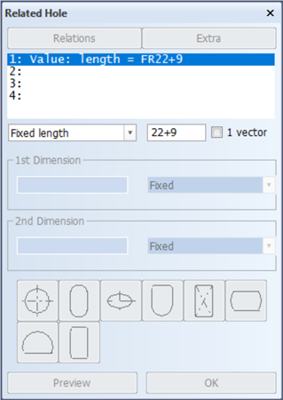
Within panel Related Hole you enter the relations of the first hole. Start with the minimum length. Notice that there is no bulkhead present that you can indicate for the minimum length. This means that for the minimum length, you have to specify a fixed value:
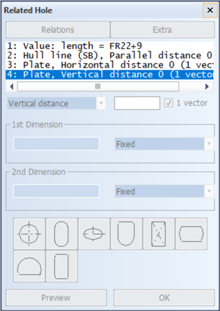
For the remaining relations you can start by indicating the hull line, the bulkhead at frame 23 and the deck 3500 respectively. When all four relations are defined, proceed to the tab Extra. Specify 4 for Amount and FR1 for Step size.
Now return to the Relations tab, and select the second hole from the left in the top row for the type of hole. Use the default values for the size of the hole by clicking OK. Because you are going to make the size of the holes depend on the construction parts surrounding them, you will redefine the height and length using percentages instead of values in millimeters. Choose Percentage from the drop-down menu for Height and Length:
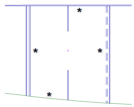
Clicking the Preview button allows you to see a preview of what the first hole will look like with these values. Click OK to place the holes.
Create Slanted View
Let's open top view 3500 and notice the two newly created longitudinal plates. What you are going to do next, is connect both longitudinal plates by creating a slanted plate in between them. In order to accomplish this, you will first need to create a slanted view that will fit exactly in between the two plates.
For this you will draw a line segment in between the two plates that you can use to indicate when creating the slanted view. In other words, the line segment will be representing the exact position of the slanted view. This is also known as the drawing plane of the plate.
Start by using the mouse to zoom in on the right side egde of plate 4620 from C.L. Now create a circle by selecting on the Draw tab the arrow under icon Circles in the Draw section to start Centre, Radius:
![]()
Click the lower line of plate 4620 to indicate the center of the circle and the upper line for the endpoint of the circle.
Now proceed to zoom in on the left side edge of plate 5280 and start the Line Segments function in the Draw section of the Draw tab:
![]()
Snap to the end point of the upper line of plate 5280 by using hot key <e> to start drawing the line segment. Snap to the circle you just drew by opening the polling menu with the right mouse button near the circle and choose the 'Tangent' snap method:
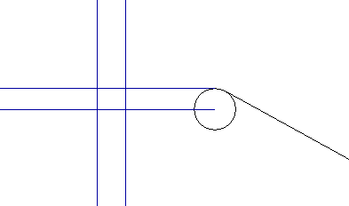
The circle represents the knuckle that will be placed to connect the two plates
Because the view you are about to create will be positioned exactly over the line segment, the thickness direction of the slanted plate will have to be from CL.
Let's create the new side view. Because you are creating a slanted side view based upon a line segment drawn in a top view, you need to select Create Side View and select the option Single slant top view. Now proceed to click the line segment. As you can see, the values indicating the position of the line segment are automatically used to determine the position of the drawing plane.
Set the value 25.5 for Min. Length and 28.5 for Max Length. The values for the minimum and maximum height should be 1500 and 3600 respectively.
Set the baseline to 1500 and click the Create button to create the slanted view.
Create Plates
When you want to create the plate, you first need to know which parts to indicate for defining the relations. You can use the 3D-Item Information function to make sure that you are indicating the bulkheads 4620 and 5280.
The plate has a thickness of 9 mm and the thickness direction is 'from CL'. Indicate both bulkheads as shown:
Insert Views
Now you will return to each of the three drawings "4620-knuckle", "knuckle-plate" and "5280-knuckle" to edit their respective areas. You will want to set the areas equal to the edges of each plate to have them be placed side by side seamlessly.
Lets open the first drawing "4620-knuckle". The boundary where "knuckle-plate" will be added is set to FR26+50. Start the Drawing Properties function in the General section:
![]()
Before you start editing your drawing area, take notice to the value that is set in the Origin field. This is the value that determines from which point of origin everything in the drawing is drawn. In order to successfully place the concerning three drawings side by side, they all need to have the same point of origin. You can use '21', as it is the point of origin of the first drawing.
Now enter for Max. Length the value FR26+50 in both the Area Construction and the Area Shape fields and click OK and save the drawing.
Now do the same thing for the "knuckle-plate" drawing. Enter FR26+50 for Min. Length and FR27+600 for Max. Length, again in both the Area Construction and the Area Shape fields.
Do not forget the set the point of origin to 21.
For drawing "5280-knuckle" you will then need to set the Min. Length to FR27+600 and the point of origin to 21.
Now the drawings are ready to be placed side by side. Return to drawing "4620-knuckle", and from the menu select Hull Application Button > Insert drawing:
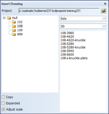
Select the 3D environment, followed by the "knuckle-plate" drawing, and it will be inserted immediately. Repeat this action for the "5280-knuckle" as well.