Frame 29 – Part 3 Profile Dimensions
Start situation – Frame 29 - Part 3 Profile Dimensions
- Profile Size - 1
- Profile Size Series
- Profile Size – 2
- Profile Size – 3
- Profile Symbols
- Profile Part Number Symbols
To complete the current drawing, you will add the size of the deck beam and the stiffeners. You will also practice additional profile dimensioning options, like adding profile symbols to the lower stiffeners and placing profile part number symbols.
End situation – Frame 29 - Part 3 Profile Dimensions
Profile Size - 1
You will now dimension the deck beam HP 140 x 8 by placing a reference with both the sizes of the deck beam and the part number on this beam.
Select from the Draw tab the icon Part Labeling in the Symbols section:
![]()
Now the hint Select item by Point, place Number/Dimension appears. This means that when you click a point near a profile, the dimension and part number of the profile will appear.
As the hint Select item by Point, place Number/Dimension suggests, you select the beam and the dimension appears with the optional part number symbol.
Note: Using the hot key <7>, will trigger the 'function dependent option' (FDO for short) Turn, which allows you to change the orientation of the dimension. This way you can determine whether you wish to have your dimension text appear parallel or perpendicular to the profile.
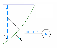
Now you can drag the dimension to the desired position on the outside of the beam, and click to see it placed. You can either place the pointing arrow perpendicular to the dimension line, or you can place it with an angle. See the following illustration:
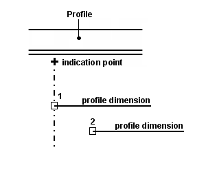
The indication point near the profile and two different dimension end points 1 and 2
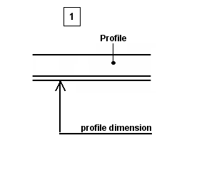
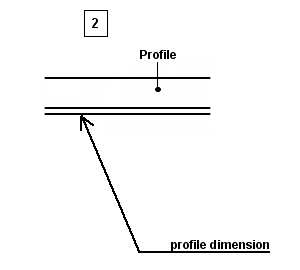
The result of the profile dimension placed, after indicating each endpoint separately
In both situations the end points are located to the right of the indication point. It works the same way when you place the end points to the left of the indication point.
Profile Size Series
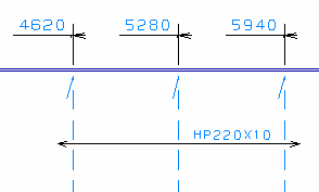
When you take a look at the upper stiffeners HP 220 x 10 on the sheet, you will notice that the three stiffeners, located at 4620, 5280 and 5940 off CL, are dimensioned by using one dimension text. Now you will practice this option by dimensioning a series of profiles.
Now let's dimension the upper stiffeners at 4620, 5280 and 5940 off CL by selecting the ribbon icon Profile Size Series on the Draw tab:
![]()
According to the hint Indicate starting-point of check-line you indicate the starting point near the left side of the stiffener at 4620 off CL. Upon the second hint Indicate end of check-line you indicate the starting point near the right side of the stiffener at 5940 off CL. After indicating both points you can position the dimension text by using the mouse. The result will be as follows:
Important: Be aware of the fact that all the profiles to be dimensioned should be of the same type and size, otherwise it could cause some confusion. For example; when dimensioning all four lower profiles using this option, the system will display for profile size HP 220 x 10 for all stiffeners, even though the profile size of the stiffener at 6600 off CL is HP 140 x 8! Therefore be careful with this option.
Profile Size – 2
You will now dimension the lower stiffener at 6600 off CL by using the Part Labeling option.
Select the ribbon icon Part Labeling:
![]()
According to the hint Select item by Point, place Number/Dimension you select the lower stiffener at 6600 off CL. Click the FDO Turn:

Aside from clicking on this FDO, you can also use hotkey <7>. This will turn the dimension as shown in the detail below. Now proceed to drag the dimension to the outside of the hull line, and click to place the profile dimension at the desired position.
Profile Size – 3
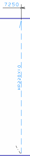
Another possibility to dimension a profile is adding the profile dimension text to the selected profile only. Although this option is not used on the sheet, you will use it to dimension the upper stiffener HP 220 x 10 at 7250 off CL.
Let's dimension the upper stiffener at 7250 off CL by selecting the ribbon icon Part Labeling:
![]()
Proceed to press the hotkey <6> to trigger the FDO Text:

According to the hint Select item by Point, place Number/Dimension, you select the upper stiffener located at 7250 off CL. By clicking the left-mouse button near the profile, a dimension without any part number or part number symbol appears, and then you can move the mouse to place the text in the desired position:
Profile Symbols
Another profile dimensioning option, which also isn't applied on the sheet, offers you the ability to add a profile symbol to a specific profile. Within this training step you will add profile symbols to the three lower stiffeners HP 220 x 10 and the remaining lower stiffener HP 140 x 8.
Select the icon Profile Symbol in the Symbols section of the Draw tab:
![]()
Following the hint Indicate profile(s) at positions where profile symbols are to be placed, you indicate the lower stiffeners one by one. Every profile symbol from here on out will automatically be placed at the same height, because all the stiffeners are attached to the same plate.
In case of the last stiffener HP 140 x 8, the profile symbol will probably end up too low. To avoid this, you select from panel Profile Symbols the option Place symbol at new height:
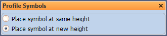
This option allows you to specify a new height at which the next profile symbol will be placed. Now indicate the lower stiffener HP 140 x 8 near its midpoint to place the profile symbol.
Profile Part Number Symbols
Finally you will add part number symbols to the first three upper and the first three lower stiffeners.
Part number symbols can be added in two ways:
- By line selection;
- By box selection.
Let's dimension the three upper stiffeners at 4620, 5280, and 7250 off CL by selecting the icon Part Labeling again:
![]()
Proceed by pressing the hotkey <7> twice in order to toggle to the FDO Number:

Now you have the ability to choose your selection method:
- Press the hotkey <8> to activate the FDO Line selection. This option enables you to draw a straight line across one or more profiles. The part number symbol(s) will be placed alongside of this reference line.
- When you press hotkey <8> for a second time, the FDO Box selection is activated. When you now 'clump' the profiles by dragging a box around them, all part number symbols will appear at the midpoint location of the stiffeners.
Note: You can only place one part number symbol per profile using these options.