Defining profile end type bevel options
The profile end shape bevels are not applied automatically by the system or the bevel generator. The user must manually choose the type of bevel to be applied from the types of bevels defined by the system administrator. Applying bevels is done with the following functions in the 3D-Contek application:
- Construction > Profiles > Modify > Green for profile end shapes
- Construction > Face Plates > Modify > Green for face plates
The system administrator has two options for setting up profile beveling. This is done in the System Management application, Construction > Weld/Bevels > Settings > Profile Beveling.
- Use standard bevels (default) – See Beveling using standard bevel types.
- Use predefined bevels – See Beveling using predefined bevels.
Beveling using predefined bevels is based on the older system of using nine standard bevel types. While maintaining consistency in beveling, using predefined bevels gives the system administrator the possibility to create customized bevels that are based on the standard bevel types, by specifying bevel properties. Up to thirty custom predefined bevels can be defined.
The two sections below explain how the system administrator can set the norms for the usage of their preferred method.
Beveling using standard bevel types
The nine standard bevel types are I, V+, V-, X, Y+, Y-, K, X+, and X-. See Bevel types.
The following configuration files must be set up to use the standard bevel types:
- beveltypes.dat and beveltypes.cmd for the first and second end shapes
- beveltypes34.dat and beveltypescmd34.cmd for the third and fourth end shapes
These files are located in the <project>\norms\cvar\weld folder. Both of the file pairs are set up similarly. Below beveltypes.cmd and beveltypes.dat are used as an example.
Configuration files
It is important that the beveltypes.dat and beveltypes.cmd files have corresponding content, so that both contain entries for the same bevel types. The beveltypes.cmd file must define (all) the same bevel types that are listed in beveltypes.dat. Inconsistencies between the two files may result in incorrect bevel information being applied by users.
-
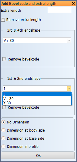
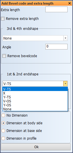
The beveltypes.dat file determines which standard bevel types are available for users in the Construction > Profiles / Face Plates > Modify > Green function, in the 1st & 2nd endshape drop-down menu, and also the order in which they appear, and the bevel type name that is displayed. It simply lists the available bevel types for the user.
Example
V-TS
X
Y-TS
V-OS
Y-OS
None
Bevel type V-TS appears first in the drop-down menu, and it is considered the default bevel type.
-
The beveltypes.cmd file defines the properties of each bevel type listed in the beveltypes.dat file. Standard bevel types are assigned bevel type numbers matching the bevel type name, and the default angle can also be set here. The user can change the angle in the Green dialog if so desired. The contents of the beveltypes.cmd file can be divided into two parts: The first part defines the content of the 1st & 2nd endshape drop-down menu and the default angle, and the second part contains the default values that are used if the user does not select any bevel.
Example
if st='V-TS' : beveltype='1';if angle='' : angle='30'
if st='X'    : beveltype='2';if angle='' : angle='30'
if st='Y-TS' : beveltype='3';if angle='' : angle='30'
if st='V-OS' : beveltype='4';if angle='' : angle='30'
if st='Y-OS' : beveltype='5';if angle='' : angle='30'
if st='None' : beveltype='6';angle='0'
exit
label 1
beveldefault=2
beveltype='2'
angle='30'
dim_location=2
exitIn the example, standard bevel type V-TS is assigned bevel type number 1, and standard bevel type X is assigned bevel type number 2, and so on. A 30 degree default angle is set for all the bevels, except type None.
The second part, starting with label 1, specifies a default bevel which the system applies if the user does not specify any. In the example case the default bevel is specified to be an X bevel, type 2 with an angle of 30 degrees, and the dimension location setting is set to Dimension at body side.
Note: The bevel type numbers set here must match the numbers of the bevel lines (B lines) in the type file of the profile end type. See Bevel for more information on defining the bevel lines in the profile end type files.
Beveling using predefined bevels
Predefined bevels are created and modified in the System Management application, Construction > Welds/Bevels > Predefined Bevels. Predefined bevels are based on the 9 standard bevel types. Predefined bevels use the basic shape of the standard bevels but their specific angles, dimensions and behavior can be customized. Up to 30 predefined bevels can be defined for users to select. The existing predefined bevels can be modified. See Predefined Bevels for information on how to add, edit and delete predefined bevels.
Note: When predefined bevels are used, the bevel angle cannot be given by the user in the user interface when adding bevels, as is the case when standard bevel types are used. With predefined bevels, the bevel angle always comes from the predefined bevel. This means that if several bevel angles are needed for an otherwise similar bevel, a separate predefined bevel must be defined for each angle.
Making predefined bevels available for users
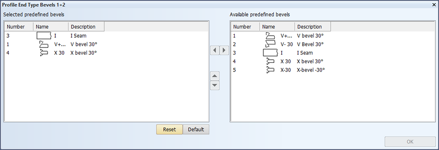
The system administrator selects in the System Management application which of the predefined bevels defined in Construction > Welds/Bevels > Predefined Bevels are available for users in the Construction > Profiles / Face Plates > Modify > Green function in the 3D-Contek application, in which order, and what is displayed as the bevel name. The name can be the same as the predefined bevel name, or it can be changed. The description can also be changed.
- Construction > Welds/Bevels > Profile End Type Bevels 1+2 for the first and second end shapes
- Construction > Welds/Bevels > Profile End Type Bevels 3+4 for the third and fourth end shapes
Configuration files
The system stores a list of the selected predefined bevels in the following configuration files, located in the <project>\norms\cvar\weld folder:
- pdbtypes12.dat for the first and second end shapes
- pdbtypes34.dat for the third and fourth end shapes
Example
3 I
1 V+ 30
4 X 30
Each line consists of the predefined bevel number and the bevel name that were set in Construction > Welds/Bevels > Predefined Bevels.
The example, if it is pdbtypes12.dat, defines that the predefined bevel number 3 appears as the first item by the name of I in the 1st & 2nd endshape drop-down menu in the Green function.