Predefined Bevels
Construction > Welds/Bevels > Predefined Bevels
Manage predefined bevels. You can add, edit, delete, and duplicate predefined bevels.
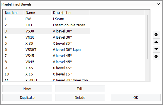
Use the arrow buttons on the right to change the order of the bevels. Each predefined bevel is assigned a bevel number according to its position on the list. The bevel number is used when defining beveling rules.
The Name and Description fields are editable directly. Click a name or description and enter the new text.
Note: Even though you can define up to 999 predefined bevels, only the first 30 will show up in the bevel selection list in the Green functions in the 3D-Contek application. This means that users can select from a maximum of 30 predefined bevels, regardless of how many predefined bevels are defined.
Bevel properties
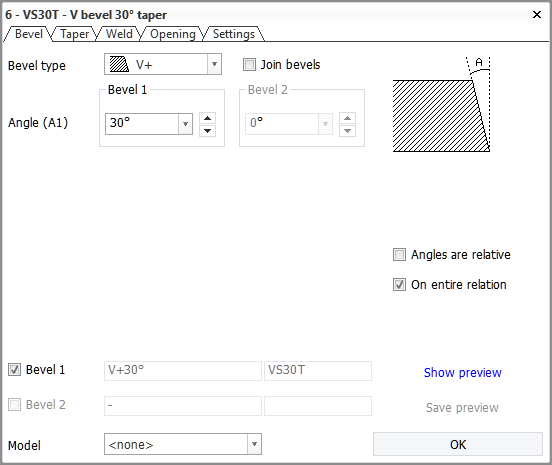
To define the properties of a predefined bevel, select the bevel and click Edit. A dialog for defining the bevel properties opens. The bevel properties are grouped into tabs. For information on the settings and options in the tabs, see Bevel properties for predefined bevels.
Settings tab
Because a predefined bevel has no knowledge of the thickness of the plate it is going to be placed on, the behavior of the bevel dimensions must be defined in advance. In case the plate thickness is different than set for Thickness here, the system adjusts the bevel dimensions according to the settings as follows:
-
Fixed – The selected dimension will not change from what is defined even if the thickness of the plate is different.
-
Remainder – The thickness difference is divided evenly between the selected dimensions. At least one dimension must be selected.
-
Percentage – The selected dimension remains a constant percentage of the total thickness of the bevel.
This setting value is useful for a symmetrical X bevel. With an X bevel, both the upper and lower bevel height should be set to Percentage, and their values would be set to half of the plate thickness.
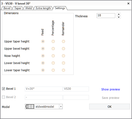
These settings are applied during the creation and recalculation of the bevel.
The selected Model is used as the icon for the predefined bevel.
Example
In the example settings below, Bevel (H1), Nose (N) and Bevel (H2) in the Bevel tab are set to 3, 4 and 3 mm, respectively. Together these result in thickness of 10, corresponding to the Thickness set in the Settings tab. H1, N and H2 represent Upper bevel height, Nose height and Lower bevel height in the Settings tab, respectively.
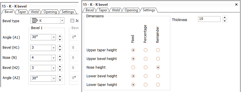
With the settings used here, if the plate thickness is other than 10 mm, the nose height and lower bevel height will stay as is, and the thickness difference will affect the upper bevel height because it is set as a Remainder dimension.
For example, if the thickness is changed to 12 mm, with the bevel dimensions defined in the Bevel tab shown in the image above, the resulting upper bevel height (H1) would be 5 mm.