Defining weld lines on selected parts
You must define the start and end points of manually added weld lines. The points are based on selected lines or arcs.
The Weld Lines dialog is shown:
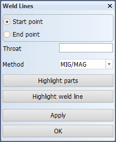
Start and End points
If Latching is activated, the point will be placed at the closest latching point to where the user specifies. A snap hotkey (e, m, or p), can be used to define the point at an intersection (see Snap keys). If the point is not located on a line or an arc, it will be placed on the nearest line or arc. The start and end points are represented by squares.
Once both the start and end points are defined, the system will try to define all of the points of the weld line to be added. It will start on the element (line or arc) nearest to the start point and check if the end point is positioned on that same element. If not, the system searches in the direction of the end point for the next element which is connected until it finds the end point on the element. If nothing can be found, the system will search the other way from the start point. If the end point still cannot be found on an element, a warning is given in the dialog window: "No weld line can be defined based on start and end point".
Weld line properties: Throat and Method
Weld properties are not retrieved from the predefined bevel in this situation so they must be specified manually.
The throat height is an edit field where a positive value needs to be entered. The throat height must be entered manually while inserting weld lines because, unlike in the single bevel function, there is no automatic function available for the throat height.
The method is presented as a combo box displaying the possible types of welding method which are available to be applied for this weld.
Highlight parts
The main and second parts are highlighted in the graphical window.
Highlight weld line
This button highlights the weld line which has been arranged to be added. If the start and end points have not both been defined, then the system cannot define a weld line and nothing will be highlighted. A message is displays in the message window in that case: Weld line is not yet defined.
Applying weld lines
After clicking either Apply or OK, a check is made if the weld points are defined properly and a positive throat height has been entered. The weld line is created if this check passes, otherwise an error message is displayed. The weld line is not presented in the drawing until after this panel is closed so it will not appear immediately after pressing Apply which does not close the panel so that the user can continue adding weld lines to the selected parts. However, the weld line will be displayed after pressing OK which will also close the function and update the drawing. If the function is closed without defining any new weld lines then no updates will be done on the drawing.