Angle markers on variable bevels
Variable bevels have different angles at their start and end points. This is usually because the beveled edge is following the hull shape, which makes a varying angle along the length of the beveled part. This difference in angle can be divided into steps with a customizable size on DXF output.
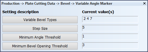
Splitting is not done in the database containing the weld lines, it is only done to simplify the output cutting data of a variable bevel. Bevel splitting is controlled by the settings in System Management > Production > Plate Cutting Data > Bevel > Variable Angle Marker:
- Variable Bevel Types for defining the bevel types that can get variable angle markers.
- Step Size for defining the step size (in degrees) in which the variable bevels should be split.
- Minimum Angle Threshold for defining the minimum angle. An interval with a smaller angle than this value will not be presented.
- Minimum Bevel Opening Threshold for defining the minimum bevel opening. Only bevels with an opening equal to or larger than this value will get variable angle markers.
This splitting is done only for certain bevel types (set by Variable Bevel Types) and when the bevel opening is equal or larger than defined by Minimum Bevel Opening Threshold. If the bevel opening is smaller than the minimum bevel opening threshold, the bevel will not be presented at all, even if the bevel type is listed in the Variable Bevel Types setting. The bevel opening is defined as the smallest gap that the bevel makes. For example, the lower bevel opening would be used in the image below:

The angle is assumed to change linearly between the start and end angles so that the splitting can be done in parts with a user defined amount of degrees. This amount is defined by Step Size setting.
Often there will be a remaining part with a difference in angle smaller than the Step Size setting. If the angle of this remaining part is smaller than a specified threshold value, defined by Minimum Angle Threshold setting, the last piece is extended to cover this remaining part. If it is equal or larger to this threshold then an extra section is added.
The splitting begins from the start angle and then works toward the end angle. For example, if the start and end angles are 10° and 37° respectively, the step size is 5° and the threshold for remaining angles is less than or equal to 2°, then the start angles of the different parts will be 10°, 15°, 20°, 25°, 30° and 35°. If the threshold were larger than 2°, then the final two sections would merge and the final section would be from 30° to 37° instead. If the start angle is larger than the end angle, so for example 37° and 10°, then the start angles of the parts will be respectively 37°, 32°, 27°, 22°, 17° and 12°. An example of applying markers according to the bevel splitting settings, from 10° to 37° with a step size of 5° and a threshold value less than 2°, is shown in the image below:

Each part has its own bevel opening. The bevel opening must be greater than the Minimum Bevel Opening Threshold. This could cause parts with a too small of bevel opening to be left out from the DXF.
A custom bevel model can be added between two consecutive pieces (shown as the blue Y in the image above).
Marker model
The user defined model (%ncgnorms%\mod2d\bvlsplt.mod) indicates the start point of each part of the split weld line. If the model is not available then no indicator is placed. When a individual part of the split weld line is not presented because of the size of the bevel opening, the parts which are presented have the above mentioned model presented at the start and end position. This does not include the original start and end positions of the original weld line.
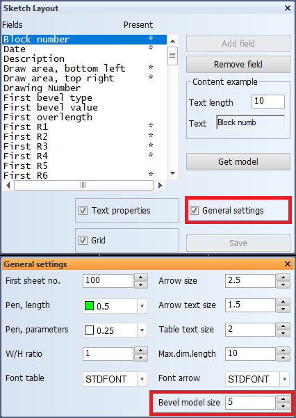
The size of the marker model can be set with the General settings > Bevel model size setting in System Management > Production > Profile Sketch > Sketch Layout. This setting sets the enlargement factor for bevel models, as well as for the variable bevel angle marker model on a profile sketch. The default value is 2. It is presumed that the model is created for scale 1:25.