Weld lines on plates and brackets
Weld lines are presented as lines if the Show weld line option is selected in the drawing properties, see Presenting weld lines. If weld status property is set to locked, then the weld line is not presented in the Hull application but is still available in the Weld Manager tool. The length of the presented weld lines depends on the way the main part is presented.
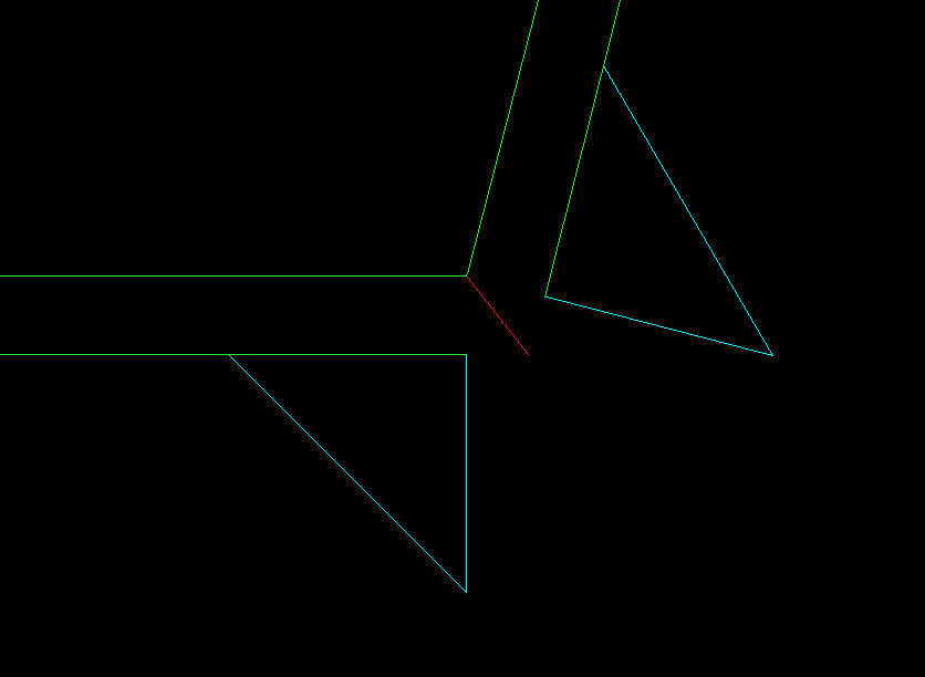
Weld lines on parts in plan view
.PNG)
Plan view: weld lines, shown in red, run between plates, represented by dashed green lines
A weld line can be in plan view. A (part of) a weld line is presented in plan view depending on if the weld lines are in the same plane as the view.
Otherwise the weld line is presented in cross section.
Weld Lines on Parts in Cross Section
Presenting a weld line in cross section is quite similar to the presentation of face plates on plates in cross section.
A weld line can cross the actual view which creates two possibilities:
- The weld line belongs to one plate
- The weld line belongs to two plates
If the weld line belongs to one plate, it will be displayed starting at the molded side of the plate and ending at the thickness side of the part.
.PNG)
Cross-section view: Length of the weld line, shown in red, is the same as the thickness of the part which is cut into a cross section by the current view
If the weld line belongs to two overlapping plates, then the weld line is presented starting at the outer intersection point of the two plates and ending at the inner intersection point of the two plates as seen below:
Weld line, shown in red, between two overlapping plates, shown in green