Insert

You can insert a Standard Component and assign a position ID attribute that matches the component type (Valve or Instrument), or you can insert any Standard Component that is allowed in the piping specification without assigning a position ID to it.
If inserting a Standard Component to a pipe that has a hole request, the commands also try to set the new piping part as the trigger object of the hole request.
When using the Valve or Instrument command, you can link the model object to one or more integration objects, which add externally provided information to the model object. For more information on integration objects and how to prepare object attributes for this purpose, see Integration object attributes.
Tip: After the insertion, you can add attributes to the model object with the Tools > Attributes > Edit command or via the Properties pane.
Valve
You can insert a valve component into the model. Using this command, the program automatically suggests the "Valve Position Id" attribute to be added to the model object.
Prerequisites
-
Optionally, an integration object for adding externally defined data to the attributes of the valve object.
Do the following:
-
On the Piping tab, in the Standard Component group, select Insert > Valve.
-
Click the pipe where you want the valve to be inserted.
-
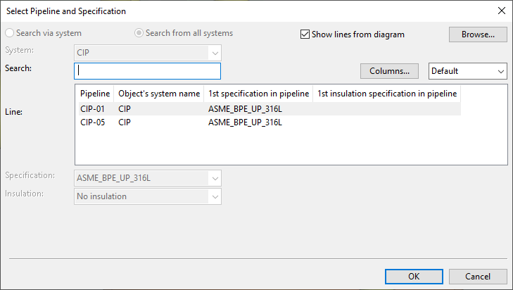
If the Select Pipeline and Specification dialog opens, select a pipeline and specification for the component.
You can use the Search field to find the required line. Also regular expressions are supported.
 Show/hide details
-
The columns that are searched are predefined. Note that the search string can also be found from a column that is not currently visible: click Columns to define which columns to show.
-
The search string can be found from any part of the target string, and the search is not case-sensitive.
Search string…
Finds…
line
strings that contain LINE, such as "MyLine-01"
-
You can use a dot to represent a single required character.
Search string…
Finds…
....line-01
strings where LINE-01 is preceded by at least four characters, such as "AA_MyLine-01"
-
You can use advanced regular expressions if you add R: to the beginning of the search string.
Search string…
Finds…
R:[ad]
strings that contain A or D, such as "DIN_H2A"
R:[a-d]
strings that contain A, B, C or D, such as "CW-001"
R:^k
strings that start with K, such as "K51"
R:[\s]
(or just R: followed by one space character)
strings that contain a whitespace character, such as "My Line 01"
Note: If the project uses P&ID integration and you are connecting the valve to the end of a pipeline that is defined in a diagram, the Show lines from diagram option is automatically selected; clear the option if you want to select a pipeline that is not defined in a diagram.
Then click OK to continue.
-
-
If the Select System and PosID dialog opens, select whether to link the valve to data obtained via integration:
-
To link the valve to an integration object, select the integration object and click OK to continue.
-
To insert the valve without linking it to integration data, click Insert Other Component.
-
-
If the Select Component dialog opens, select the valve component. If you are using P&ID integration, note the following:
- You see a list of valves that the diagram defines for the selected pipeline. (This is similar to inserting equipment—see About linking integration objects to equipment.)
- If the required component has been defined in P&ID by using integration rules (see Catalog mapping) or by selecting the component from COS, the selection is automatic. Otherwise, select the valve component manually.
Then click OK to continue.
-
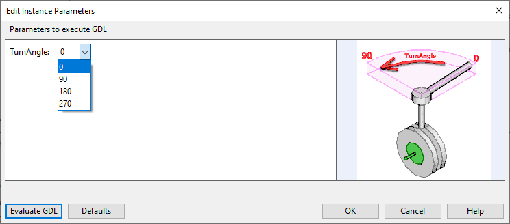
If the Edit Instance Parameters dialog opens, define the instance parameter values of the component. You can click Evaluate GDL to see a preview of the changes.
Then click OK to continue.
-
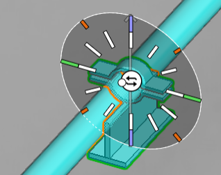
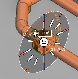
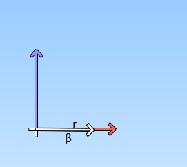
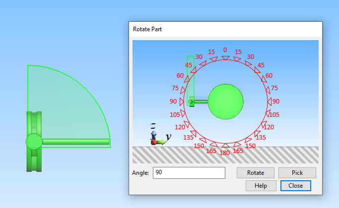
The work view displays a direction wheel for defining the orientation (which way the connections are facing) and the rotation of the component. You can switch to the next orientation by clicking the center of the wheel, and you can rotate the component by clicking a direction on the wheel or using the Enter rotation angle (Alt+R) command to define the rotation value. Then press Enter to continue.
Tip: You can adjust rotation and orientation also after the insertion. See Change Orientation.
-
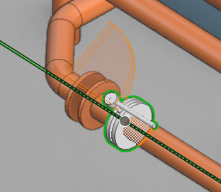
Unless you are inserting the valve to the end of a pipe, the cursor is now locked to move along the length of the pipe. Slide the component to the intended location and press Space or click to confirm the location.
-
If the new location requires a different bolt set or gasket than the previous location, you might be prompted that "you need to manually set bolt owner". This can happen, for example, if you slide a butterfly valve and place it between flanges that use different specifications. In these situations, the specification is taken from the "bolt owner" object, and if there is no bolt owner, you can use the Bolt owner: Set tool to give this role either to the component or to one of the valves, as applicable. For more information, see Flanged connections.
-
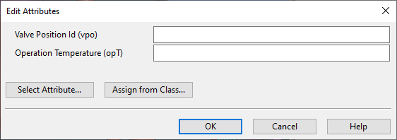
The Edit Attributes dialog opens. You can add and remove attributes and define their values, as required. If P&ID integration is used, you can link P&ID attributes to Plant Modeller. All mapped data is automatically filled in: if you are inserting a valve that has an externally defined position ID, then that ID is automatically filled in.
Then click OK to complete the insertion process.
Instrument
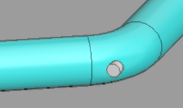
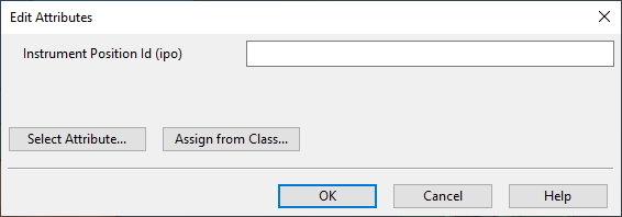
You can insert an instrument outlet such as a welding nipple into the model. Using this command, the program automatically suggests the "Instrument Position Id" attribute to be added to the model object.
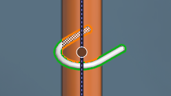
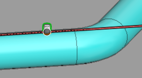
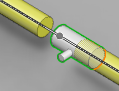
Typically, the component is inserted to a straight pipe, but you can also insert the instrument to an elbow. In this case, the command draws two additional points that mark the locations where the surface of the elbow intersects with the centerline of the straight pipe.
Prerequisites
-
Optionally, an integration object for adding externally defined data to the attributes of the valve object.
Do the following:
-
On the Piping tab, in the Standard Component group, select Insert > Instrument.
-
To insert the component to a straight pipe, do the following:
Show/hide details
-
Move the cursor near the pipe and press Space or click to select the pipe.
-
If the Select System and PosID dialog opens, select whether to link the new component to data obtained via integration:
-
To link the component to an integration object, select the object and click OK to continue.
-
To insert the component without linking it to integration data, click Other PosID.
-
-
If the Select Component dialog opens, select the required component and click OK.
-
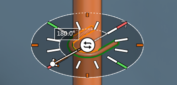
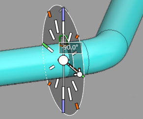
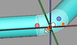
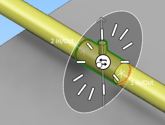
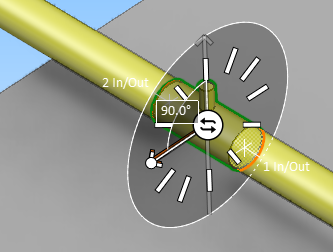
The work view displays a direction wheel for selecting where the component should be placed on the perimeter of the pipe. Click the required direction or use the Enter rotation angle (Alt+R) command to type the value. Then press Enter to continue.
-
If the Edit Instance Parameters dialog opens, define the instance parameter values of the component. You can click Evaluate GDL to see a preview of the changes. Then click OK to continue.
-
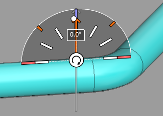
The work view displays a direction wheel for selecting how the component should be aligned in regard to the surface of the pipe. Click the required direction or use the Enter rotation angle (Alt+R) command to type the value. Then press Enter to continue.
-
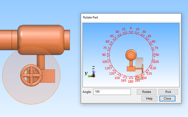
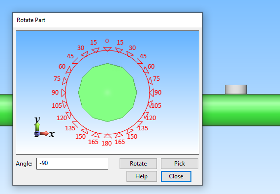
You are prompted to define the rotation of the component (not relevant if the cross section is symmetrical). You can rotate the component around its centerline by clicking a direction in the Rotate Part dialog or by typing the angle value and clicking Rotate.
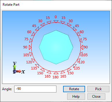
Then click Close to continue.
-
The cursor is now locked to move along the length of the pipe. Slide the component to the intended location and press Space or click to confirm the location.
-
-
To insert the component to an elbow, do the following:
Show/hide details
-
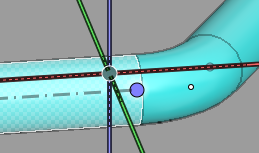
Move the cursor near one of the two orange points on the surface of the elbow, so that a direction arrow appears next to the point, and press Space or click to select the location.
-
If the Select Component dialog opens, select the required component and click OK.
-
If the Edit Instance Parameters dialog opens, define the instance parameter values of the component. You can click Evaluate GDL to see a preview of the changes. Then click OK to continue.
-
You are prompted to define the rotation of the component (not relevant if the cross section is symmetrical). You can rotate the component around its centerline by clicking a direction in the Rotate Part dialog or by typing the angle value and clicking Rotate.
Then click Close to continue.
-
-
The Edit Attributes dialog opens. You can add and remove attributes and define their values, as required. If P&ID integration is used, you can link P&ID attributes to Plant Modeller. All mapped data is automatically filled in: if you are inserting a component that has an externally defined position ID, then that ID is automatically filled in.
Then click OK to complete the insertion process.
Component without position ID
This command allows you to insert any Standard Component that does not require a specific position ID attribute or linking to integration objects.
Do the following:
-
On the Piping tab, in the Standard Component group, select Insert > Component without position ID or press Alt+S.
-
Click the pipe where you want the component to be inserted.
-
If the Select Pipeline and Specification dialog opens, select a pipeline and specification for the component. Then click OK to continue.
-
If the Select Component dialog opens, select the required component and click OK.
-
If the Edit Instance Parameters dialog opens, define the instance parameter values of the component. You can click Evaluate GDL to see a preview of the changes. Then click OK to continue.
-
The work view displays a direction wheel for defining the orientation (which way the connections are facing) and the rotation of the component. You can switch to the next orientation by clicking the center of the wheel, and you can rotate the component by clicking a direction on the wheel or using the Enter rotation angle (Alt+R) command to define the rotation value. Then press Enter to continue.
-
Unless you are inserting the component to the end of a pipe, the cursor is now locked to move along the length of the pipe. Slide the component to the intended location and press Space or click to confirm the location.
Select System and PosID
The Select System and PosID dialog allows you to link a Standard Component to an integration object so that the model object would get a position ID and other data attributes from another software program where that component has already been defined. If integration is not applicable, you can choose the Insert Other Component option and define the required attributes manually.
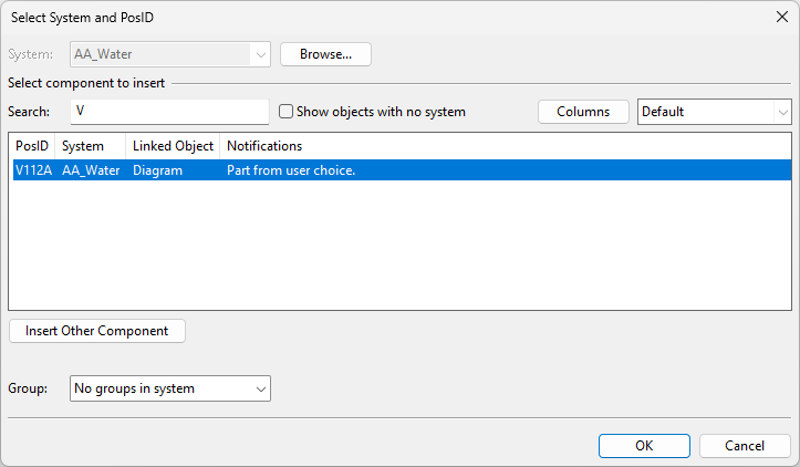
The Select System and PosID dialog opens automatically when you are inserting a Standard Component and the project contains integration objects that are not linked to a model object. If the dialog opens but is empty, either the integration objects are assigned to a different System than what is currently selected or they have no System assignment.
By default, the dialog displays these columns, but you can add more by clicking Columns:
-
PosID – The position ID defined in the integration object.
-
System – The System of the integration object.
-
Linked Object – The type of the integration object: "EDM", "Electrical", or "Diagram".
-
Notifications – Information about the integration object. Red notification text indicates that there is an error that prevents linking the object.
Notification
Details
Part from EDM.
EDM object defines which component model will be used.
Part from EPD.
EPD object from a diagram defines which component model will be used.
Part from user choice.
EPD object has no component model defined. (You will select the component model in the next step.)
You can filter the list by System or any data column:
-
System – If System is not fixed, you can select a specific System to see only integration objects that are assigned to that System. If the System you are looking for is not listed, click Browse to find it.
-
Show objects with no system – Select this option if you want the list to show integration objects that have no System assignment.
-
Search – You can filter the list by entering a text string in this field. The program looks for the given text string from all columns, including columns that are not visible, and displays the matching integration objects.
Select the integration object to use from the list, and click OK to continue.
Insert context menu commands
When inserting a Standard Component, the context menu contains the following commands.
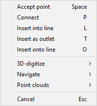
Accept point (Space) | Connect (P) | Insert into line (L) | Insert as outlet (T) | Insert onto line (O)
Accept point (Space)
You can use the Accept point (Space) command to select the nearest piping part.
If a piping part is not near enough, the command selects the current cursor location. Inserting a Standard Component into empty space prompts you to define the following:
-
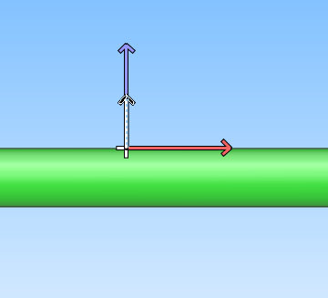
Select the direction of the component from the on-screen tool.
-
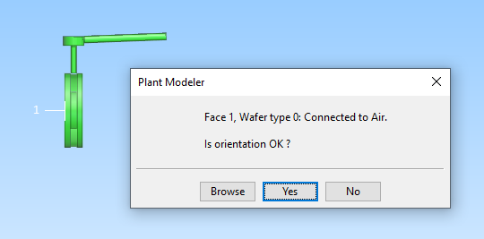
Select the orientation of the component.
-
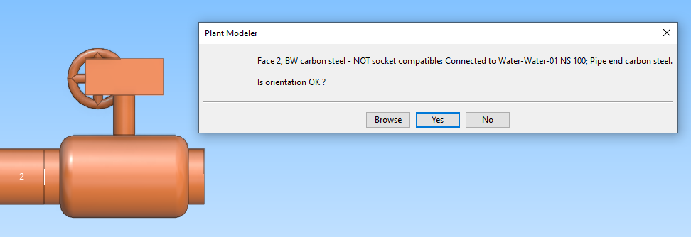
Browse – Temporarily closes the dialog and allows you to browse the work view; press Esc or Space or click to return to the dialog.
-
Yes – Accepts the orientation.
-
No – Switches to the next orientation.
-
-
Select whether to rotate the component around its centerline.
Connect (P)
You can use the Connect (P) command to insert a Standard Component to the end of a pipe. The insertion direction is automatically taken from the target pipe.
You are prompted to define the following:
-
Select the orientation of the component (which side to connect to the pipe).
-
Browse – Temporarily closes the dialog and allows you to browse the work view; press Space or click to return to the dialog.
-
Yes – Accepts the orientation.
-
No – Switches to a different orientation.
-
-
Select whether to rotate the component around its centerline.
Insert into line (L)
Tip: This is a legacy command. Instead of using this, you can simply click the target pipe and select the Standard Component to be inserted—the program automatically applies the correct insertion method for the given component.
You can use the Insert into line (L) command to insert, for example, a valve into a straight pipe. If the insertion point is too close to the end of the pipe, the component is automatically moved to the end.
If the connection faces require flanges, the program uses the nominal size of the pipe to find a suitable Short Code ("f", "f1", "f2"… until "f50") from the active specification, and inserts flanges to the connections.
You are prompted to define the following:
-
Select the orientation of the component by clicking the center of the on-screen tool. Alternatively, you can use the Change orientation (O) command to switch the orientation. Press Enter to confirm the orientation.
-
Select the rotation angle of the component by clicking the required direction on the on-screen tool. Alternatively, you can use the Enter rotation angle (Alt+R) command to type the rotation value. Press Enter to confirm the rotation angle.
-
Slide the component to the intended location. You can use context-menu commands to select whether the reference point is in the center or at either end of the component. Press Enter to confirm the location.
Insert as outlet (T)
Tip: This is a legacy command. Instead of using this, you can simply click the target pipe and select the Standard Component to be inserted—the program automatically applies the correct insertion method for the given component.
You can use the Insert as outlet (T) command to insert outlet components to pipes.
Before starting this command, you must select the exact insertion location from the surface of the pipe.
You are prompted to define the following:
-
Select the insertion direction from the on-screen tool.
-
Select whether to rotate the component.
Insert onto line (O)
Tip: This is a legacy command. Instead of using this, you can simply click the target pipe and select the Standard Component to be inserted—the program automatically applies the correct insertion method for the given component.
You can use the Insert onto line (O) command to insert, for example, a bushing sleeve or a pipe support that is connected to a pipe. Components that are inserted this way are deleted if the associated pipe is deleted.
The command tries to select a straight pipe that is near the picked insertion point, takes the nominal size from the pipe, and determines the part ID of the component from the specification of the pipe. The component is assigned to the same Pipeline and System as the target pipe.
If the pipe is slightly sloped, you are prompted whether the component should ignore the pipe's deviation from a main axis; if you select Yes, the component will be at a slightly different angle than the pipe, which is sometimes wanted for simple pipe supports.
If the geometry type of the component is DM_GT_TEE, DM_GT_CROSS, DM_GT_LATERAL or DM_GT_YPIECE, then the picked insertion point is used as the center point (point 4 or 5) of the component. Otherwise (if the component does not have a center point), the first node of the component is positioned at the insertion point, so that the direction from the node matches the corrected direction.
You are prompted to define the following:
-
If inserting a component where orientation is important, select the orientation by clicking the center of the on-screen tool. Alternatively, you can use the Change orientation (O) command to switch to a different orientation.
-
If inserting a component where rotation is significant, select the rotation angle by clicking the required direction on the on-screen tool. Alternatively, you can use the Enter rotation angle (Alt+R) command to type the rotation value.
-
Slide the component to its intended location. Press Enter to confirm the location.