Functional Model Templates

Functional Model Templates enable easy re-use of a set of objects. A functional model template can contain a set of objects, a 2D drawing, an eBrowser model, and possibly metadata as attributes.
To create a new functional model template, you select a set of objects and define an origin for the set. When inserting an instance of the functional model template into a 3D model, you select a location and orientation for the model and map the Systems and Lines. You can also change the position IDs of named equipment and valves.
The components of a functional model template are saved in the library database and they can be used in all projects that use the same library. It is also possible to export a template from one library and then import it to another, using CX export/import. Successful import requires that the target project contains the specifications used by the components in the template.
Creating a functional model template
You can create a functional model template for a set of objects that you plan to re-use in several projects.
Do the following:
-
On the Tools tab, in the Manage group, select Functional Model Templates. The Functional Model Templates object browser opens.
-
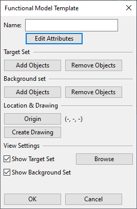
Select New > Functional Model Template. The Functional Model Template dialog opens.
-
Define the contents of the template.
 Show/hide details
-
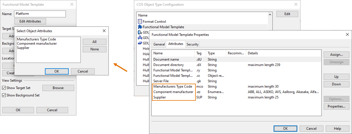
Name – Enter a descriptive name for the template.
-
Edit Attributes – Select this to add additional attributes to the template.
You can only add attributes that your administrator has assigned to the "Functional Model Template" COS object type.
-
Target Set – Use the Add Objects and Remove Objects commands to define the set of model objects to be included in the template.
-
Background set – Use the Add Objects and Remove Objects commands to define a set of background objects for the template. Background objects are only displayed in the template drawing, they are not included when inserting an instance of the template into the 3D model area.
-
Location & Drawing
-
Origin – Select this to pick an origin point for the template. The origin is used as a reference point when inserting an instance of the template into the 3D model area.
-
Create Drawing – Select this to create a 2D drawing of the template. You are prompted to select the document sheet, to select annotation property defaults, to create standard E-projections, and then the document editor opens for finalizing the document. Save the document locally.
-
-
View Settings
-
Show Target Set is selected by default. Clearing it removes the template objects from the preview window.
-
Show Background Set is selected by default. Clearing it removes the background objects from the preview window.
-
-
-
Make sure the template contains all that is needed—you cannot modify the contents later. Then click OK to continue.
-
If you are prompted that there is more than one possible surface shading rule, select the rule to use for shading the objects of the template.

You can now view the template as an eBrowser model and insert one or more instances of the template into the 3D model area.
Viewing a functional model template as eBrowser model
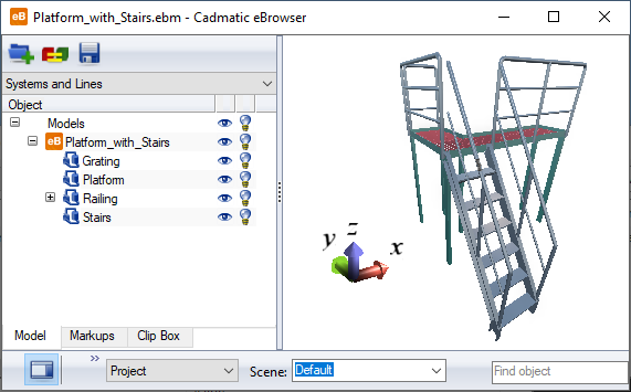
Plant Modeller automatically creates an eBrowser model for functional model templates.
Do the following:
-
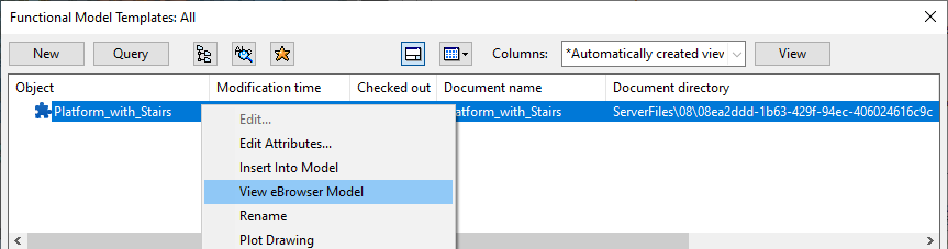
On the Tools tab, in the Manage group, select Functional Model Templates. The Functional Model Templates object browser opens.
-
Right-click the template whose eBrowser model you want to see and select View eBrowser Model from the context menu.
The model opens in eBrowser.
Printing a functional model template
Functional model templates have a drawing that can be printed.
Do the following:
-
On the Tools tab, in the Manage group, select Functional Model Templates. The Functional Model Templates object browser opens.
-
Right-click the template whose drawing you want to print and select Plot Drawing from the context menu. The Print Setup dialog opens.
-
Select the printer, paper size and orientation, and click OK. The Plot dialog opens.
-
Define the plot settings, and click OK.
Inserting a functional model template into the 3D model
You can insert an instance of a functional model template into the 3D model area.
Prerequisites
Do the following:
-
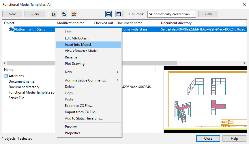
On the Tools tab, in the Manage group, select Functional Model Templates. The Functional Model Templates object browser opens.
-
Right-click the template you want to insert into the 3D model and select Insert into Model from the context menu.
-
You are prompted to pick the location where you want the origin of the template to be placed.
-
You are prompted to define a direction for the X-axis and the Y-axis of the template.
-
You are prompted to enter a name for the Model Group. Type the name and click OK.
-
If the Importing Objects dialog opens, click Map Attributes to verify the attribute mappings or Next to continue with default mappings and then click Finish when the import is completed.
-
You are prompted "Is location OK?". If you click No, you can move the template in the model, and then press Enter to accept the new location.
-
The Map systems and pipelines dialog opens. Map the entities as described in Map Systems and Pipelines, and then click OK.
Map Systems and Pipelines
In the Map systems and pipelines dialog, you can map the objects of a functional model template to the Systems and Lines of the current project. The left pane lists the Systems defined in the functional model template. When you select a System, the right pane lists the objects that are assigned to it.
-
Template objects whose System already exists in the target project are automatically mapped to that System. If a given System does not exist in the target project, you can either map the object to one of the existing Systems or create a new System. You can create new Systems via the Edit systems and pipelines context-menu command.
-
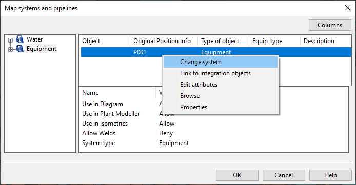
You can change the System mapping of non-piping components via the Change system context-menu command.
-
Lines (pipeline, ductline, cable tray) must be mapped even if they already exist the project.
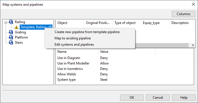
In the picture below, "Railing~00" is a temporary pipeline definition and the user must map the objects to an existing pipeline or create a new one to be able to continue. Using the command Create new pipeline from template pipeline / Create new ductline from template ductline / Create new cable tray from template cable tray allows the new line to inherit attributes from the line in the template.
-
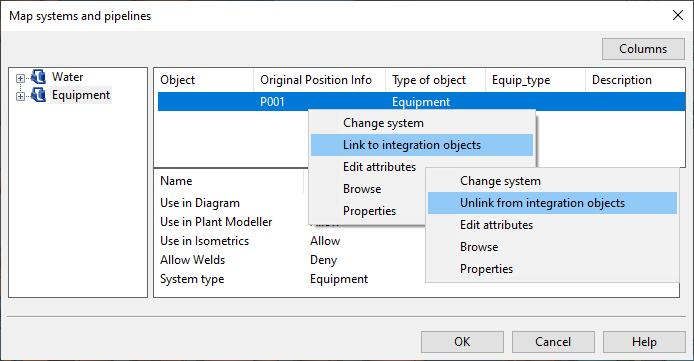
Equipment can be linked to integration objects via the Link to integration objects context-menu command. This opens the Select System and PosID dialog for selecting the integration object.
Existing links can be removed via the Unlink from integration objects command.