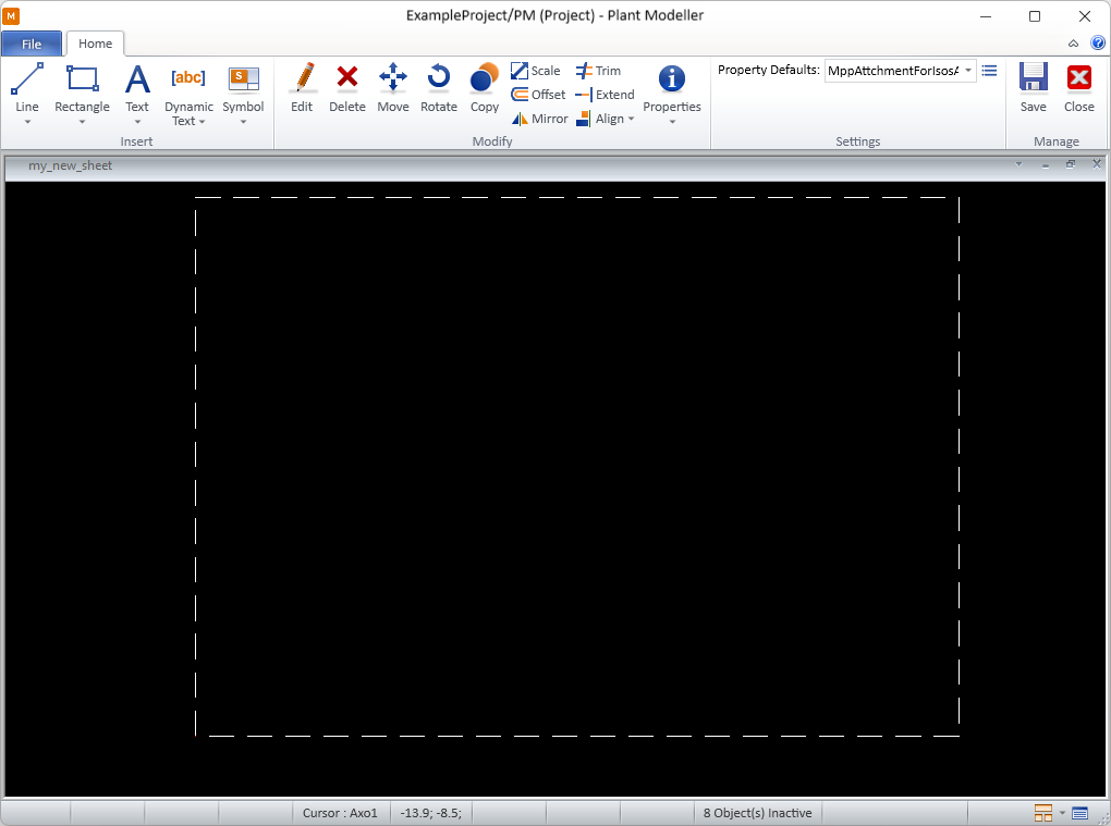
Drawing sheet's block editor
In the Drawing sheet editor, you can use the Block tools to add DWG blocks to the drawing sheet. When you add or open a block, the block editor toolbar appears. Closing the block editor restores the standard drawing sheet editor toolbar.
Using the block editor tools, you can customize the block's contents by inserting lines, rectangles, static or dynamic text, and 2D symbols. Dynamic text allows you to include DWG block attributes in the drawings, with their values automatically retrieved from CADMATIC document attributes.
Insert
On the Home tab of the drawing sheet's block editor, the Insert group contains the following tools.
Line | Rectangle | Text | Dynamic Text | Symbol
Line
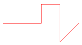
You can insert lines that consist of one or more straight line segments and have the properties described in Line Properties.
By default, the line being inserted gets its properties from the currently selected Property Defaults. You can override these project defaults by making session-specific adjustments via Modify > Properties > Line/Rectangle properties. You can also adjust the properties of individual lines, both during and after the insertion.
You can modify existing line objects also with the generic Modify tools.
Insert line | Apply line properties
Insert line
You can insert lines into the block.
Do the following:
-
In the Insert group, click the line insertion tool
 or select Line > Insert line.
 -
Pick the start point of the line.
-
You can now change the line's properties by selecting Properties from the context menu.
-
Navigate to the next intended line point and pick that point. You can add as many points as needed and change the direction of the line at any point.
You can enable the Ortho (F8) option to ensure that lines are horizontal or vertical.
-
When you have added the last point of the line, press Enter to complete the line.
Apply line properties
You can apply predefined Line Properties to existing lines.
Do the following:
-
In the Insert group, select Line > Apply line properties.
-
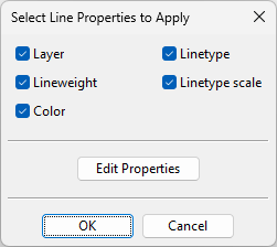
Pick one or more lines and press Enter. The Select Line Properties to Apply dialog opens.
-
All properties are selected by default; change the selections if appropriate.
-
To review or edit the properties before applying them, click Edit Properties.
-
Click OK.
Rectangle
You can draw rectangles that have the properties described in Line Properties.
By default, the rectangle being inserted gets its default properties from the currently selected Property Defaults. You can override these defaults by making session-specific adjustments via Modify > Properties > Line/Rectangle properties. You can also adjust the properties of individual rectangles, both during and after the insertion.
You can modify existing rectangles also with the generic Modify tools.
Insert
You can insert rectangles into the block.

Do the following:
-
In the Insert group, click the rectangle insertion tool
 or select Rectangle > Insert.
 -
Pick the first corner of the rectangle.
-
You can now change the rectangle's line properties by selecting Properties from the context menu.
-
Pick the opposite corner point to complete the rectangle.
Apply properties
You can apply predefined Line Properties to existing rectangles.
Do the following:
-
In the Insert group, select Rectangle > Apply properties.
-
Pick one or more rectangles and press Enter. The Select Line Properties to Apply dialog opens.
-
All properties are selected by default; change the selections if appropriate.
-
To review or edit the properties before applying them, click Edit Properties.
-
Click OK.
Text
You can insert static multi-line text strings that have the properties described in Text Properties.
By default, the text being inserted gets its properties from the currently selected Property Defaults. You can override these defaults by making session-specific adjustments via Modify > Properties > Text properties. You can also adjust the properties of individual texts, both during and after the insertion.
You can modify existing texts also with the generic Modify tools.
Insert
You can insert texts into the block.
Do the following:
-
In the Insert group, select Text > Insert.
-
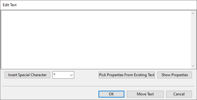
Pick the location where to add the text. The Edit Text dialog opens.
-
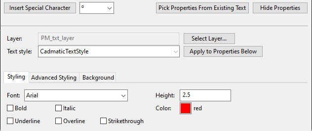
In the text pane, type the text to be inserted. If you need to insert special characters into the text, use the Insert Special Character tool or paste a Unicode character from the clipboard, but be aware that not all fonts support all special characters.
-
You can specify the text's appearance by using predefined text properties or formatting the text manually.
-
You can pick all the properties from an existing text. To do this, click Pick Properties From Existing Text, pick the source text and press Enter.
-
You can select a predefined style from the Text style field and click Apply to Properties Below to apply the style to the text.
-
You can edit any of the text's properties manually.
-
-
You can move the text by clicking Move Text and picking the new location.
Tip: While moving the text, you can rotate the text at 90° increments. Press the + (plus) key for counter-clockwise rotation and the = (equal) key for clockwise rotation, or select the respective command from the context menu.
-
Click OK.
-
Press Enter if you want to insert another text.
Apply properties
You can apply predefined Text Properties to existing texts.
Do the following:
-
In the Insert group, select Text > Apply properties.
-
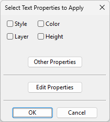
Pick one or more texts and press Enter. The Select Text Properties to Apply dialog opens.
-
Select which properties to apply to the texts.
-
Style – Select this option to set the target text's Text style field to the value defined in Text Properties. This does not immediately apply the style to the target text; you can apply the style later by opening the target text's properties and clicking Apply to Properties Below.
-
Layer – Select this option to set the target text's Layer field to the value defined in Text Properties.
-
Color – Select this option to set the target text's Color field to the value defined in Text Properties.
-
Height – Select this option to set the target text's Height field to the value defined in Text Properties.
-
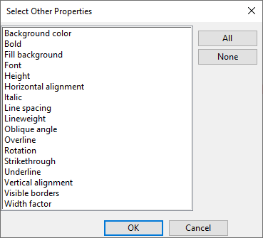
Other Properties – This button opens a list of all the properties that can be applied to the target text. Select the ones to be applied, and click OK.
-
-
To review or edit the properties before applying them, click Edit Properties.
-
Click OK.
Dynamic Text
You can insert text that updates dynamically into the block, provided that the documents using this drawing sheet contain the necessary attributes to populate the dynamic text.
Insert dynamic text | Manage dynamic texts
Insert dynamic text
You can insert dynamic text into the block.
Do the following:
-
In the Insert group, select Dynamic Text > Insert dynamic text.
-
Pick the origin point for the text. The Edit Dynamic Text dialog opens.
-
Specify the dynamic text properties described in Edit Dynamic Text as well as the normal Text Properties that define the text's appearance.
-
Click OK.
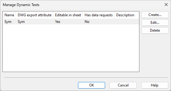
Manage dynamic texts
You can manage the dynamic texts of the block you are editing.
Do the following:
-
In the Insert group of the block editor, select Dynamic Text > Manage dynamic texts. The Manage Dynamic Texts dialog opens, listing the dynamic texts of this block.
-
Select what to do:
-
To create a new dynamic text, click Create and follow the steps outlined in Insert dynamic text.
-
To edit the selected dynamic text, click Edit and modify the properties described in Edit Dynamic Text and Text Properties.
-
To delete the selected dynamic text, click Delete.
-
-
Click OK.
Edit Dynamic Text
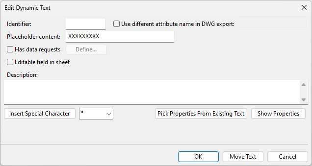
The Edit Dynamic Text dialog contains the following settings.
|
Setting |
Description |
|---|---|
|
Specify a unique string (1–3 characters) to identify the dynamic text within the drawing sheet. By default, this string will also be used as the name of the DWG block attribute during drawing export, unless a different attribute name is specified. |
|
|
Select this option to define a specific DWG block attribute name for the dynamic text during drawing export. If this is not specified, the value of the Identifier field will be used. |
|
|
You can use this function to evaluate how the dynamic text will look on the document page. Enter a text string that represents the kinds of values the dynamic text will usually display. Note: If no data requests are defined, the placeholder string itself will appear in the drawings. |
|
|
Select this option and click Define to open the Data Request Definition dialog and define the data requests that will update the dynamic text. |
|
|
Select this option to allow manual editing of the dynamically generated text through the Edit fields of sheet command of the document editor. |
|
|
Optionally, enter a description to be shown in the Manage Dynamic Texts dialog. You can use the Insert Special Character tool to insert special characters into the description. |
After defining the dynamic text settings above, you can adjust the text's appearance by copying Text Properties from another text or by clicking Show Properties to define them manually.
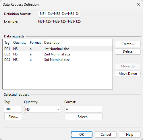
Data Request Definition
In the Data Request Definition dialog, you can define the data requests that will update the dynamic text when the drawing sheet is used in a drawing.
Do the following:
-
Create the required data requests as follows.
-
In the Data requests section, click Create.
-
In the Selected request section, define the request.
-
Tag – Find or type the tag of the attribute whose value to retrieve into the column.
-
Quantity – Select the quantity type of the value. For more information, see Quantity definitions and their units of measure.
-
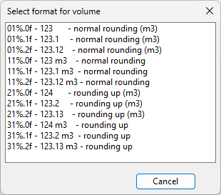
Format – Specify how to format the retrieved value, if applicable.
-
-
-
In the Definition format field, ensure that each data request is represented with a formatting code that specifies how to present the retrieved values.
You can insert the caret ^ character between formatting codes to split the values into separate rows. For example, if you have three data requests that retrieve nominal sizes 1–3, you may use something like "NS1-%s NS2-%s NS3-%s" to put them all in the same row or "NS1-%s^NS2-%s^NS3-%s" to split them into three rows.
Symbol
You can insert 2D symbols that have the properties described in Symbol Properties.
By default, the symbol being inserted gets its properties from the currently selected Property Defaults. You can override these defaults by making session-specific adjustments via Modify > Properties > Symbol properties. You can also adjust the properties of individual symbols, both during and after the insertion.
You can modify existing symbols also with the generic Modify tools.
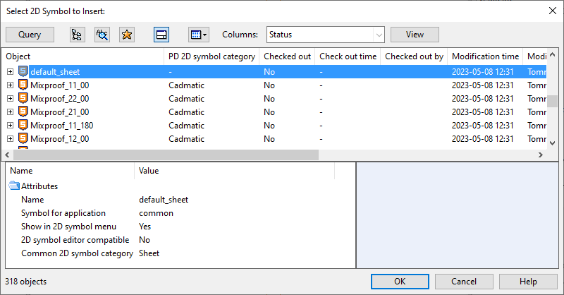
Insert
You can insert 2D symbols into the block.
Do the following:
-
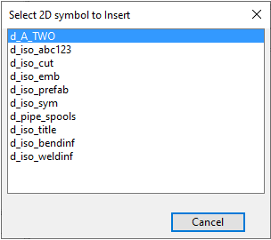
In the Insert group, select Symbol > Insert. The Select 2D Symbol to Insert object browser dialog opens.
-
Select the symbol to be inserted and click OK.
-
If the 2D symbol script defines multiple symbols, a secondary dialog opens. Click the name of the required symbol.
-
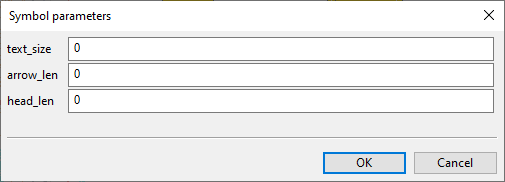
If the symbol requires parameters, the Symbol parameters dialog opens. Enter the required parameters and click OK.
-
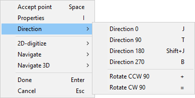
Move the symbol to the intended location. While moving the symbol, you can right-click the view to open the context menu which allows you to rotate the symbol or access the symbol properties.
-
Pick the origin point where to add the symbol.
-
Press Enter if you want to insert another symbol.
Apply properties
You can apply predefined Symbol Properties to existing 2D symbols.
Do the following:
-
In the Insert group, select Symbol > Apply properties.
-
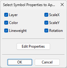
Pick the symbols to which to apply the properties and press Enter. The Select Symbol Properties to Apply dialog opens.
-
All properties are selected by default; change the selections if appropriate.
-
To review or edit the properties before applying them, click Edit Properties.
-
Click OK.
Modify
On the Home tab of the drawing sheet's block editor, the Modify group contains the following tools.
Edit | Delete | Move | Rotate | Copy | Scale | Offset | Mirror | Trim | Extend | Align | Properties
Edit
You can modify an object.
Do the following:
-
In the Modify group, click
 Edit. The cursor displays as a crosshair.
-
Pick the object you want to edit.
-
Edit the object.
-
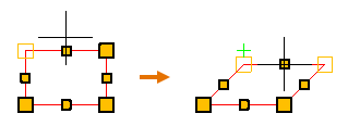
If you picked a line or rectangle, its line points are displayed.
You can click and drag or use the additional tools to customize the object.
 Show/hide details
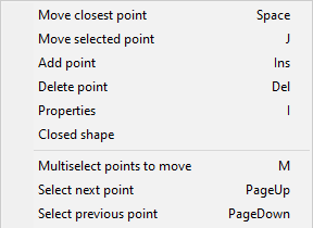
The context menu contains the following tools:
-
Move closest point (Space) – This is the same as clicking with the left mouse button; the command selects the point closest to the cursor and allows you to move that point. If you click a line segment's middle point, the command selects both end points of that segment.
Repeat the command or click to accept the move.
-
Move selected point (J) – Allows you to move the selected line point, regardless of where the cursor is when you start the command.
Repeat the command or click to accept the move.
-
Add point (Ins) – Adds a new line point.
-
Delete point (Del) – Deletes the selected line point.
-
Properties (I) – Opens the properties dialog described in Line Properties. The changes you make only affect the selected line object.
-
Closed shape – Connects the end points with one or more additional line segments to form a closed shape. If the line is already closed, removes a line segment to make the line open-ended.
-
Multiselect points to move (M) – Allows you to select several points from a line object. Press Enter to accept the set and then move the selected points to the required location.
-
Select next point (PageUp) – Selects the next line point.
-
Select previous point (PageDown) – Selects the previous line point.
-
-
If you picked text, the Edit Text dialog opens, displaying the properties that were defined when inserting the Text. Modify the properties as required.
-
If you picked dynamic text, the Edit Dynamic Text dialog opens. Modify the properties as required.
-
If you picked a 2D symbol, its origin point is displayed.
You can click near the origin point to start moving the symbol, or you can use the additional tools to customize the object.
Show/hide details
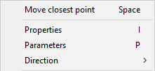
The context menu contains the following tools:
-
Move closest point (Space) – This is the same as clicking with the left mouse button; the command selects the origin point and allows you to move the symbol.
-
Properties (I) – Opens the properties dialog described in Symbol Properties. The changes you make only affect the specified symbol object.
-
Parameters (P) – Opens a symbol-specific dialog for changing the parameters of the symbol.
-
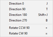
Direction – Opens a menu for selecting the direction of the symbol.
-
-
-
Press Enter to accept the modified object.
The cursor turns into a cross-hair again to indicate that you can pick another object for editing.
-
Press Enter or Esc to stop editing the block's objects.

Delete

You can delete a set of objects.
Do the following:
-
In the Modify group, click Delete.
-
Pick the objects that you want to delete and press Enter. The selected objects are deleted.
-
Press Enter again if you want to delete another set of objects.
Move

You can move one or more objects to a different location.
Do the following:
-
In the Modify group, click
 Move.
Move. -
Pick the objects you want to move and press Enter.
-
Pick the base point and a second point. This defines the direction and the offset and moves the objects.
-
You can pick another point, as many times as needed, to move the objects incrementally.
-
Press Enter to complete the move operation.
-
Press Enter again if you want to move another set of objects.
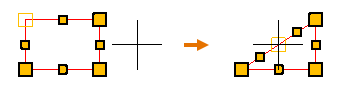
Rotate

You can rotate one or more objects around the specified base point.
Do the following:
-
In the Modify group, click
 Rotate.
 -
Pick the objects you want to rotate and press Enter.
-
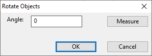
Pick the base point around which to rotate the objects. The Rotate Objects dialog opens.
-
Enter the rotation angle. Alternatively, click Measure to measure the angle using two base points and directions. Then click OK.
-
Press Enter if you want to rotate another set of objects.
Copy

You can make one or more copies of a set of objects. The copies are created in a given direction, with the same amount of offset between the copies.
Note: You cannot use this command on dynamic text.
Do the following:
-
In the Modify group, click
 Copy.
Copy. -
Pick the objects you want to copy and press Enter.
-
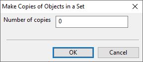
Pick the base point and a second point. This defines the direction and the offset for the copying, and the Make Copies of Objects in a Set dialog opens.
-
Enter the number of copies to create and click OK.
-
Press Enter if you want to copy another set of objects.
Scale

You can use the Scale tool to change the scale of one or more objects.
Note: You cannot use this command on dynamic text.
Do the following:
-
In the Modify group, click
 Scale.
 -
Pick the objects you want to rescale and press Enter.
-
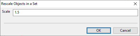
Pick the base point for the rescaling. The Rescale Objects in a Set dialog opens.
-
Enter the scaling factor to use and click OK.
Offset

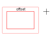
You can copy an existing line or rectangle object so that the new object is inserted at a user-defined offset on either side of the original object. For example, if the original object is a rectangle, you can use this command to insert a smaller rectangle inside or a larger rectangle outside the original object.
Note: You cannot use this command on dynamic text.
Do the following:
-
In the Modify group, click
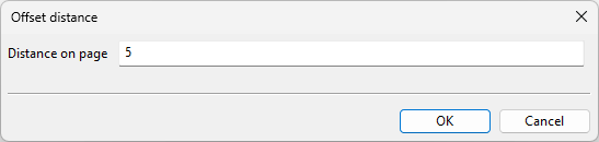
 Offset. The Offset distance dialog opens.
 -
Specify the distance from the original object to the new object, and click OK.
-
Click the object that you want to copy.
-
Move the cursor to that side of the original object where you want the new object to be placed, and click to accept the insertion.
Mirror

You can mirror one or more objects. You can choose whether to keep the original objects after the mirroring.
Note: You cannot use this command on dynamic text.
Do the following:
-
In the Modify group, click
 Mirror.
 -
Pick the objects you want to mirror and press Enter.
-
Define the mirror line by picking the first point (the line rotates around this point) and the second point.
-
You are prompted whether to keep the source objects. Select Yes to keep them or No to delete them.
Trim

You can remove a part of a line, up to the point where it intersects with another straight line or a rectangle.
Note: You cannot use this command on dynamic text.
Do the following:
-
In the Modify group, click
 Trim.
Trim. -
Click the line you want to trim.
-
Click the part you want to remove from the line.
Extend

You can extend the end of a line to the boundary of another straight line or a rectangle.
Note: You cannot use this command on dynamic text.
Do the following:
-
In the Modify group, click
 Extend.
 -
Click the line you want to extend.
-
Move the cursor in the direction you want the line to extend, and click to accept the insertion.
Align

You can align the top, bottom, left or right sides of a set of objects.
Note: You cannot use this command on dynamic text.
Do the following:
-
In the Modify group, select
Align and then the side to align. -
Pick the objects you want to align and press Enter.
The object that is farthest in the given direction stays where it is, and the other objects in the set are aligned with it.
Properties

The Properties drop-down menu contains tools for temporarily changing the default properties of the insertion tools and for changing the properties of existing objects.
Current properties | Objects in a set | Set properties in a set
Current properties
The Insert commands use the Annotation Property Defaults settings currently selected in the Property Defaults field when inserting new text or applying default properties to existing text. You can override the project defaults of the following entities in the current editing session:
-
Line/rectangle
-
Text
-
Symbol
That is, changing these properties via the Properties drop-down menu will make them the new defaults in the current editing session. The original default values will be restored when you close the drawing sheet's block editor.
For more information on the different properties, see Annotation Properties.
Objects in a set
In the Properties menu, the Objects in a set section contains tools for changing the properties of several objects at the same time.
Apply properties
You can apply the current default properties to a set of objects. The default properties can be:
-
The default properties in Annotation Property Defaults.
-
The default properties of this editing session. That is, if you have modified the properties as described in Current properties, then those settings are used as the default properties until you close the block editor.
Do the following:
-
In the Modify group, select Properties > Apply properties.
-
Pick the objects whose properties you want to change and press Enter.
The relevant properties are applied to the specified objects.
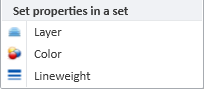
Set properties in a set
In the Properties menu, the Set properties in a set section contains tools for setting a specific layer, color, or lineweight to several objects at the same time, regardless of their object type.
Do the following:
-
In the Modify group, select Properties and then Layer, Color, or Lineweight.
-
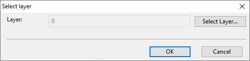
Pick the objects to include in the set and press Enter. A dialog opens for selecting the new value.
-
Select the property value to assign and click OK.
Settings
On the Home tab of the drawing sheet's block editor, the Settings group contains the following tools.
Property Defaults
Select the Annotation Property Defaults to use for the various elements of this drawing sheet.
Manage
On the Home tab of the drawing sheet's block editor, the Manage group contains the following tools.
Save
This command saves the block locally.
Close
This command closes the block editor and displays again the Drawing sheet editor.