Special 3D iso symbol definition
There may be standard components where the orientation of the connection points does not match normal CADMATIC geometry types (DM_GT_*). Usually, these connection points are not in a single plane, and therefore conventional isometric symbols are not suitable for them. In these cases, you can define a special isometric symbol for the component by specifying the attribute 'Special 3D iso symbol definition' in the dimension table or the corporate catalog.
To use the 'Special 3D iso symbol definition' attribute, the geometry type must be DM_GT_FLEXCOMP, and the component must have at least two connection points.
The value of the attribute is a CADMATIC tag record where each tag–value pair is separated with a semicolon, values can be subdivided with commas, and the record ends with a double semicolon:
tag1 value1;tag2 value2; ... tagN valueN;;
Tags
These tags can be used in the attribute definition.
| Tag | Value | Description |
|---|---|---|
|
"shr" |
shorten |
Shortens a line that is drawn to a part point by the given value. Affects all line drawing commands that come after the shorten command and end at a node point. |
|
"lin" |
p1,p2 |
Draws a line from point p1 to point p2. |
|
"mli" |
p1,p2,p3,p4 |
Draws a line from the middle of line p1–p2 to the middle of line p3–p4. |
|
"mlp" |
p1,p2,p3 |
Draws a line from the middle of line p1–p2 to point p3. |
|
"mpd" |
p1,p2,dir,length |
Draws a line with the given length, from the middle of line p1–p2 to the given direction. |
|
"ref" |
p1,p2 |
Sets the reference point of the part to the middle of line p1–p2. |
|
"scl" |
scale |
Sets the scale of the symbol to the given value. |
|
"cir" |
radius,p1,p2 |
Draws a circle with the given radius and center point in the middle of line p1–p2. |
|
"cpd" |
radius,p1,p2,dir,length |
Draws a circle that has the given radius and whose center point is defined by direction ("dir") and distance ("length") from the middle of line p1–p2. |
-
p1–p4 are integers that select a connection point by its index in the GDL component, starting from 1.
Note: Tags that calculate the middle point between two connection points (p1,p2) can also be given a single connection point (p1,p1). For example, "mpd 1,2,x,10" draws a line from the middle of p1 and p2 to X direction, whereas "mpd 1,1,x,10" draws the line directly from p1 to X direction.
-
dir specifies a direction with "x" or "y" or "z", using "-" to indicate the negative direction.
-
scale, length, radius and shorten are decimal numbers in the range from 0.0 to 100.0.
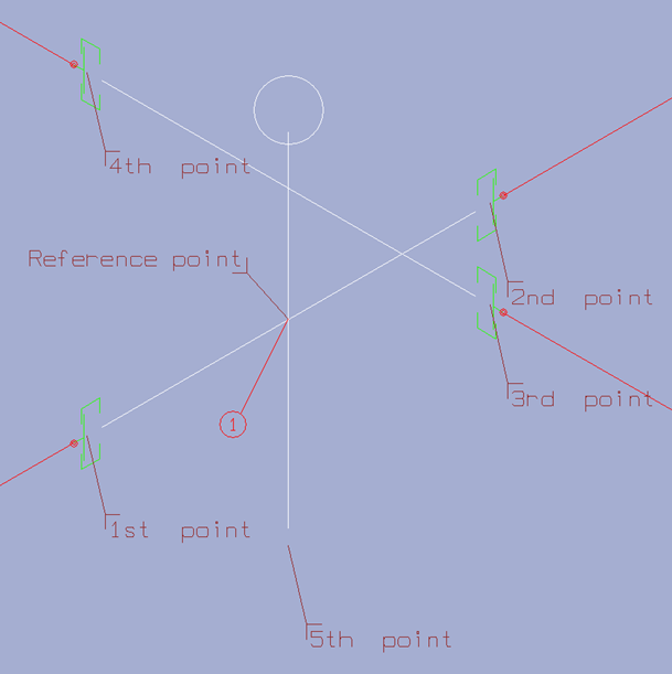
Example
This example shows the special symbol of a multi-body valve "Alfa-Laval 22-90" with 5 connection points, drawn with white color.
scl 1.2;ref 1,2;lin 1,2;lin 3,4;mli 1,2,3,4;mlp 1,2,5;mpd 3,4,z,50.0;cpd 5.0,3,4,z,70.0;;
Piping Isometrics & Spools specific attributes in dimension table
Piping Isometrics & Spools specific attributes in corporate catalog