Automatic Dimensions
The automatic dimensions feature can insert dimension lines for the following object types in the drawing views of the active document.
-
Beams
-
Equipment (centerline must first be added)
-
Pipes
The dimension lines are generated with rules that specify which objects and drawing views to include in the process. You can use a single rule for multiple views or a different rule for each view, as required.
Selecting a rule from the dialog displays how many objects in total are targeted by the rule, how many of them are equipment without a centerline marking, and how many of them are object centerlines that have not been dimensioned yet.
Performing automatic dimensioning
You can run automatic dimensioning for specified drawing views in the active document.
Before generating the dimension lines, you can use the automatic dimensions tool to add centerlines to the equipment that needs to be dimensioned. For top views, the tool will add both a vertical and horizontal centerline; these centerlines go through the origin point and are always axis-aligned. For side views, it only adds the vertical centerline by default. However, if the component model has a node named 'CL', the tool will add both a vertical and horizontal centerline to all views; these centerlines go through the GDL node and they follow the object if it is rotated. This approach helps to prevent the tool from adding unnecessary dimensions to equipment.
Prerequisites
-
The project administrator has defined the Annotation Property Defaults to be used for the centerlines and dimension lines.
-
The drawing views that need to be dimensioned are equipped with Grid Lines.
Do the following:
-
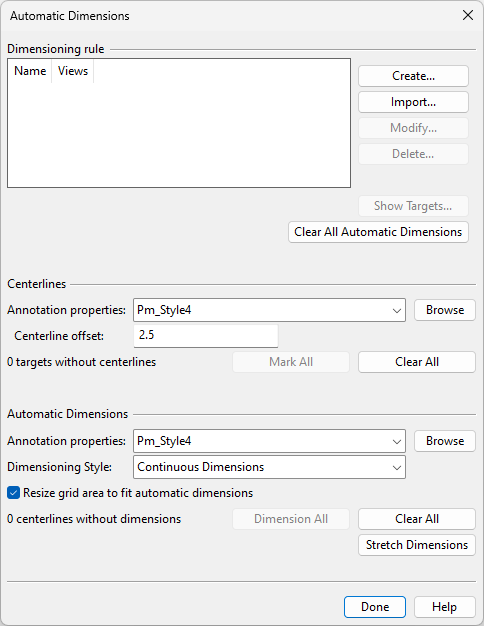
On the Home tab of the document editor, click Automatic Dimensions. The Automatic Dimensions dialog opens.
-
Define the dimensioning rules for this document.
-
Create – Opens the Dimensioning Rule dialog for creating a new dimensioning rule.
-
Import – Allows importing existing dimensioning rules from another document. If a rule by the same name already exists in this document, you can save the imported rule with another name.
-
Modify – Opens the selected dimensioning rule for editing.
-
Delete – Deletes the selected dimensioning rule.
-
Show Targets – Opens the Automatic Dimensioning Targets dialog where you can review which objects will be dimensioned by the selected dimensioning rule and exclude objects that should not be dimensioned.
-
Clear All Automatic Dimensions – Select this if you want to delete all existing centerlines and dimension lines added by this tool, from all drawing views in the active document.
-
-
Add centerline markings to the equipment. This is a mandatory step for dimensioning the equipment.
-
Annotation properties – Select the annotation property defaults for marking the centerlines.
-
Centerline offset – Specify the length of the centerline marking (0.5–5 mm).
-
Mark All – Select this to add centerline markings to all equipment identified by the selected rule in the corresponding views.
-
Clear All – Select this to remove centerline markings from all equipment in the views targeted by the selected rule.
-
-
Add the dimension lines.
-
Annotation properties – Select the annotation property defaults for the dimension lines.
-
Dimensioning Style – Select the dimensioning style to use:
-
Continuous Dimensions – See Continuous dimension.
-
Baseline Dimensions – See Baseline dimension.
-
Basepoint Dimensions – See Basepoint dimension.
-
-
Resize grid area to fit automatic dimensions – If selected, the dimensioning process will try to resize the grid area so that the dimensions will fit better into it.
-
Dimension All – Select this to add dimension lines to all objects identified by the selected rule in the corresponding views.
-
Clear All – Select this to remove dimension lines from all objects in the views targeted by the selected rule.
-
Stretch Dimensions – Select this to adjust the distances of the dimension lines manually. Press Esc to return to the dialog.
-
-
Click Done.
Dimensioning Rule
The Dimensioning Rule dialog is used to specify what to include in the automatic dimensioning process.
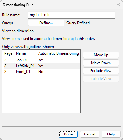
Specify a rule name and define the set of objects to include in the operation.
-
Rule name – Enter a unique, descriptive name for this rule. The name cannot contain spaces or special characters.
-
Query – Click Define to open the query editor and define the selection query. For general information on queries, see Queries.
Views to dimension
Specify which of the document's drawing views the rule should process and in which order.
-
Move Up, Move Down – The dimensioning tool will add object centerline markings and dimension lines based on the order of the drawing views in this dialog. If an object appears in multiple views, only the view with the highest priority will show its dimensions on the given axis. Move drawing views up to increase or down to decrease their priority.
-
Exclude View, Include View – The dimensioning tool will only process the drawing views specified to be included in the dimensioning process.
Automatic Dimensioning Targets
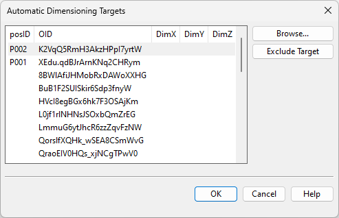
The Automatic Dimensioning Targets dialog lists the objects selected by the query of the dimensioning rule. For each object, the dialog shows the position ID, the COS OID, and the status of dimensions in the X, Y, and Z reference planes. Selecting rows from the dialog highlights the corresponding objects and their dimension points in all drawing views.
-
Browse – Allows browsing the drawing. Press Esc to return to the dialog.
-
Exclude Target – Automatically modifies the query to exclude the selected objects from it. To include the objects again, you must modify the query manually.