GDL for standard components
The geometry for a standard part such as a valve, flow meter or support is defined in the GDL model. The GDL is created as parametrized. The values for the parameters are defined in Dimension Tables. Normally standard components are stored in the library, not in the project database.
There are different ways to start modeling or editing the GDL of standard parts.
- In Plant Modeller, you can start the Component Modeller from your Plant Modeller area. Select File > Environment > Component Modeller, then in the Manage Component Model Objects dialog browse to [library] > Standard Components and open an existing GDL model or select New > GDL for Standard Part.
- In the CADMATIC desktop, select Parent > Object > Library and Project Databases, browse to [library] > Components > Catalog Parts > Geometry, and open an existing GDL model or select New > GDL for Standard Part.
Modeling a standard component
-
In Plant Modeller, select File > Environment > Component Modeller.
-
In the Manage Component Model Objects dialog, browse to [library] > Standard Components, and select New > GDL for Standard Part.
-
Pick the origin of the component.
-
Select the object attributes.
-
Select the geometry type. See Geometry types.
-
Define the connection points.
-
In Component Modeller, click Parameters and define the parameters.
- DN size(s).
- Parameters needed in the current geometry type.
- Other needed parameters.
-
Model the standard part with primitives. Remember to parametrize 'o'.
-
Save.
About the geometry of standard components
-
The main direction of a pipe is the X-axis.
-
The secondary direction is the Z-axis (e.g. the direction of the hand lever of a valve).
-
The origin of the component is node point 1.
-
Required parameters:
- The first parameter(s) are nominal size(s).
- Parameters required by the geometry type.
- Other parameters required to build the geometry.
-
Minimum value for the parameters is 1 mm.
-
For flanges the gasket-face is the X-positive end.
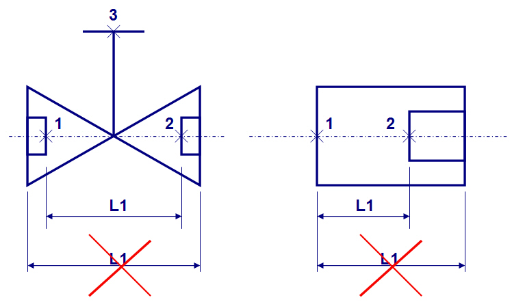
Note: The length dimensions required by geometry types are distances between node points. With threaded or socket welded parts the lengths are not the length of the component, but the distance between node points.
Note: Connection points that are not along the center line of the run pipe can be of any type. Connection points that are along the center line of the pipe must be of type DM_CT_AUXPNT.
Modeling a service space for standard component
When you insert a 3D object of type Standard Component (a valve, for example), Plant Modeller will check the referenced GDL to see if it defines also a Service Space model. If so, the Service Space will also be created as a separate 3D Space object. Due to being associated with the Standard Component, they stay together in operations like move, rotate and delete.
While editing the GDL object you can also model the Service Space geometry. First create the 3D primitives that model the Service Space geometry. Then on the Component Modeller tab, select Scope > Mark Service Space. As the last step, select the primitives for the new Service Space.
The primitives modeling the Service Space will change to transparent and apply the color as defined in Options.
You can use Scope > Remove Markings to reset any marked primitive back to normal.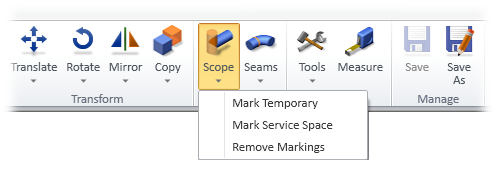
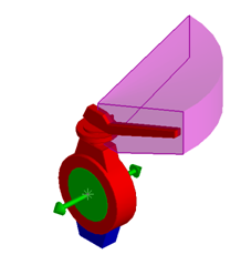
A butterfly valve with a Service Space defined for the hand lever:
Note: Service Spaces can also be modeled separately and attached to a Standard Component in the 3D model. See Service space.