Penetration settings
In [project] > Specifications > Construction > Penetration Settings, project administrators can add, modify, and delete settings for multi-pipe penetrations. Designers select which settings to use when they insert a multi-pipe penetration as described in Multi-pipe penetration.
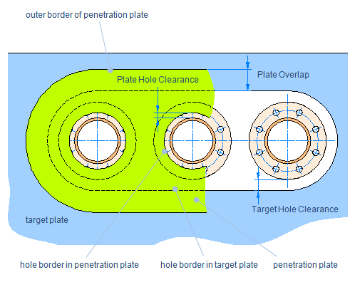
Penetration settings define what kind of clearance values to use when the penetrating pipe has a certain Nominal Size, and how much overlap there is between the 'target plate' (hull plate) that is being penetrated and the 'penetration plate' that is added onto the target plate to make the penetration watertight.
Defining Penetration Settings
Perform the following to define penetration settings.
Do the following:
-
In the Project Environment dialog, go to [project] > Specifications > Construction > Penetration Settings.
-
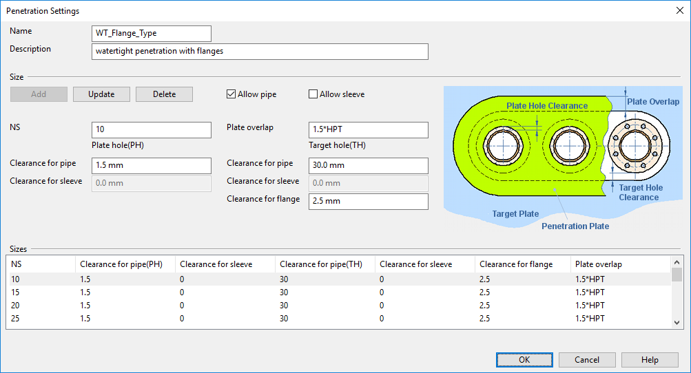
Select New > Construction Settings to create new penetration settings, or double-click an existing settings object to edit it. The Penetration Settings dialog opens.
-
Enter a name and description. Make sure that these provide enough information to the designers so that they can select appropriate settings for each penetration. The name can also be used in BOM to specify penetration type.
-
In the Size section, you can specify the following information for each Nominal Size of pipes that are to pass through the penetration.
You must select one of these settings (or both):
-
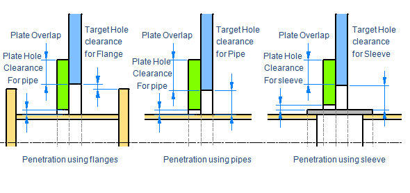
Allow pipe – If selected, the multi-pipe penetration can have specific clearance settings for pipes that do not have flanges. You can specify pipe clearance settings for the penetration plate and the target plate separately.
-
Allow sleeve – If selected, the multi-pipe penetration can have specific clearance settings for pipes that require a sleeve but do not have flanges. Designers can then add a sleeve to the penetration, and select whether to cut the pipe or let it pass through the sleeve. You can specify sleeve clearance settings for the penetration plate and the target plate separately.
Define pipe size and plate overlap:
-
NS – Nominal Size of the penetrating pipe.
-
Plate overlap – Distance from the edge of the target hole to the edge of the penetration plate.
Note: Overlap can be determined as a fixed value or relative to either 'HPT' (hull plate thickness) or 'PPT' (penetration plate thickness). These values are evaluated when the plate is created; for example, if the thickness of the hull plate is 20 mm, then plate overlap defined as 1.5*HPT equals 30.
Define clearance values for Plate hole (PH) and Target hole (TH):
-
Clearance for pipe – Distance from the outer diameter of the pipe to the hole in the penetration plate (PH) or target plate (TH).
-
Clearance for sleeve – Distance from the outer diameter of the sleeve to the hole in the penetration plate (PH) or target plate (TH).
-
Clearance for flange – Distance from the outer diameter of the flange to the hole in the target plate (TH).
Note: A flange that is next to a penetration must have the outer diameter as the first diameter in the dimension table. Otherwise the size of the hole created in the target plate will be incorrect.
Enter the required values and then click Add if adding a new Nominal Size or Update if updating an existing setting.
-
-
When all required Nominal Sizes are specified, click OK to close the penetration settings editor.