Implementing a custom template
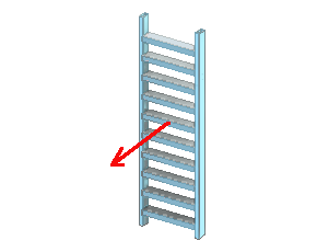
In this example custom template implementation, we will walk you through the process of creating a custom structural unit template called 'MyLadder', a simple vertical ladder without mounting legs.
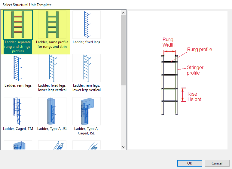
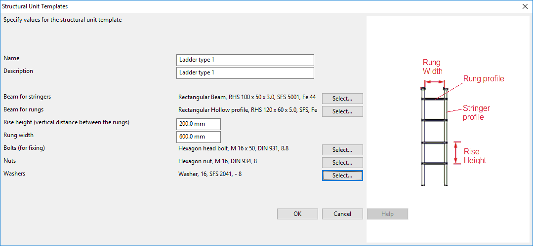
This implementation provides two interface definitions, meaning that project administrators can create new Construction Settings objects from two types of templates. Selecting a template opens the Structural Unit Templates editor where administrator can define the static parameters of the structural unit to create.
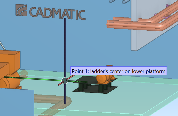
When inserting a ladder into the 3D model, designers are prompted to define these run-time parameters:
- Point 1 – the center point of the bottom of the ladder
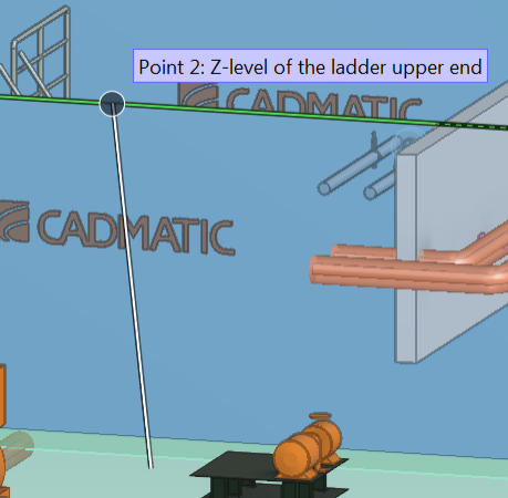
- Point 2 – the top height of the ladder (z-maximum)
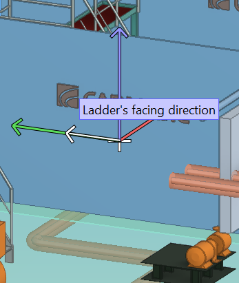
- Direction – the facing direction of the ladder (rotation around its local z-axis)
The main steps of the custom template creation process are described in the following sections:
Creating the interface definitions
The creation of a custom structural unit template starts from creating the interface definitions and saving them in the project database.
An interface definition is a list of standard CADMATIC style tag records where each tag record defines one interface. The tags that can be used are described below.
|
Tag |
Description |
|---|---|
|
ifc |
Name of template interface The name inside this object and in the file %PMS_HOME%\pm\setup\SuInterfaceIndex.txt must be unique as the data in these two sources will be merged at run-time. |
|
prm |
Prompt This text is shown when selecting the template type. It is also used as the default description for associated Construction Settings objects. |
|
tmb |
Thumbnail bitmap (64 x 64) The thumbnail image should illustrate the type of the structural unit. It is shown in the object browser if View Mode is set to 'Thumbnails'. |
|
icn |
Icon (94 x 94) The icon should illustrate the functionality of the interface function. It is shown when selecting the template and creating a new Construction Settings object. It is also shown when designer selects the Construction Settings object to create a structural unit. |
|
dim |
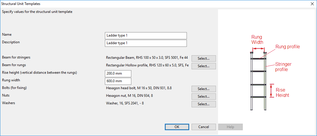
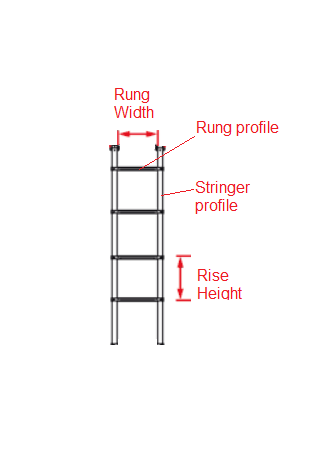
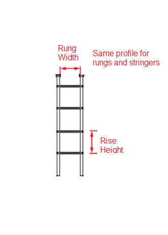
Bitmap with parameter legend (330 x 460) The image should illustrate the type of the structural unit and use suitable symbols to indicate the configurable parameters. It is shown in the Structural Unit Templates dialog where you edit the Construction Settings object. |
|
sei |
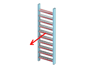
Preview bitmap (290 x 230) The preview image is shown in the preview pane of the object browser when designer selects the Construction Settings object to create a structural unit. |
|
scf |
Name of script file The script file retrieves the template-specific parameters and builds the 3D model of the structural unit. |
|
vld |
Validator (optional) Validates user-defined parameters when designer accepts the parameter values of the template. Values:
|
|
bef |
Anchor for positioning custom template in template selection list At run time, built-in templates and custom templates are merged into one table that defines the order of the items in the template selection list. By default, all custom templates are listed at the end, but using the 'bef' tag allows the custom template to be positioned in a specific location. Values:
|
In this example, we create two interface definitions. 'MyLadder_01' allows creating ladders where rungs and stringers use a different profile, and there are also extra materials (bolts, nuts, washers). 'MyLadder_02' uses the same profile for the whole construction and has no extra materials.
Do the following:
-
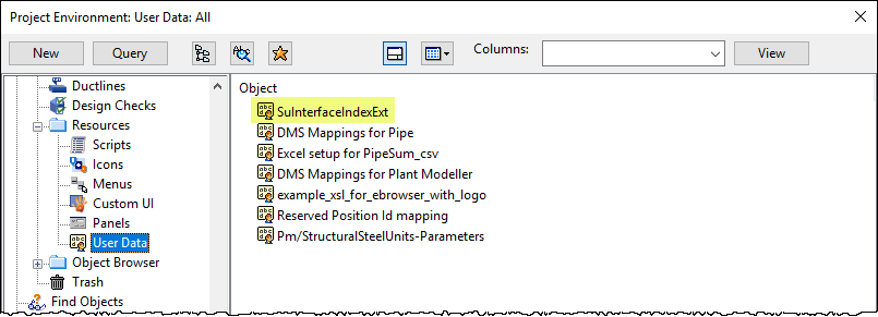
In the Project Environment dialog, browse to [project] > Resources > User Data.
-
If the 'SuInterfaceIndexExt' configuration object does not exist, select New > User Data to create it. When creating the object, set the 'User Data for application' attribute to 'pm'.
-
Open the 'SuInterfaceIndexExt' configuration object for editing, and copy the following interface definitions into the editor.
 Show/hide interface definitions
ifc MyLadder_01; prm Ladder, separate rung and stringer profiles; tmb MyLadder_01_tmb.bmp; icn MyLadder_01.bmp; scf MyLadder; dim MyLadder_01_dim.bmp; sei MyLadder_01_sei.bmp; bef *; ; ifc MyLadder_02; prm Ladder, same profile for rungs and stringer; tmb MyLadder_02_tmb.bmp; icn MyLadder_02.bmp; scf MyLadder; dim MyLadder_02_dim.bmp; sei MyLadder_02_sei.bmp; bef *; ; -
Click OK to close the editor.
Result
Creating the builder script
Developing the builder script is the major part of creating a custom structural unit template. The script implements functions that the Structural Unit Designer kernel calls back when the user does one of the following:
- Creates or edits a Construction Settings object for a structural unit.
- Inserts a structural unit into the 3D model.
The script call-back function names are fixed, based on the value of the 'ifc' tag in the interface definition. Here we assume that this value is 'MyLadder_01'.
The complete builder script that we use in this example is available in 'MyLadder' script. We strongly recommend that you examine how the script works, but below you can find descriptions of the mandatory function interfaces used in the script.
Script call-backs for managing construction settings
GetTemplateParametersOf_MyLadder_01( handle param_defs_h )
This function gets the definitions of the static parameters to be stored in the Construction Settings object: data types, prompts, value ranges, and default values.
Output:
|
param_defs_h |
Array of parameter properties |
When project administrator edits a Construction Settings object to define parameter values for the structural unit, the editor tool loads these parameter properties into the user interface. Thus different kinds of parameters and parameter properties can use the same editor component.
Parameter properties are defined using utilities in the script header include/ParamFormUI.h, and therefore this header file has to be included to the builder script. The utilities are described in ParamFormUI utilities.
Note: The parameters 'Name' and 'Description' need to be defined for all templates.
Do not use any of the fixed tags of the interface definition as tags of parameter properties.
Script call-backs for creating the structural unit 3D model
The Structural Unit Designer kernel calls these functions when a designer is inserting a new structural unit and has selected a Construction Settings object.
GetSystemIdOf_MyLadder_01( handle tmpl_header_tr_h, handle params_tr_h)
This function returns the ID of the System to which the structural unit group and its 3D objects will be assigned. (The example script returns '18' because in the project used for developing the script it was the System ID of Steel.)
Input:
|
tmpl_header_tr_h |
A handle to the header tag record of the template |
|
params_tr_h |
A handle to the parameters tag record |
GetDefaultGroupNameOf_MyLadder_01( handle tmpl_header_tr_h, handle params_tr_h)
Creating a structural unit creates a structural unit group and assigns the 3D objects of the structural unit to this group. This function returns a character string for the suggested default name of the new structural unit group. Designer can change the value, but it must be a valid group name that is not used anywhere else in the distributed project. Typically, the name consists of two parts—static text (unit name) and dynamically updated numerical value—that together make the name unique.
|
tmpl_header_tr_h |
A handle to the header tag record of the template |
|
params_tr_h |
A handle to the parameters tag record |
MyLadder_01( int system_id, handle config_tr_h, unit_set_h, int n_attrs, attrs_h, int n_emats, extramaterials_h )
This function prompts the designer to provide run-time parameters and then builds the 3D model of the structural unit.
Input:
|
system_id |
System ID |
|
config_tr_h |
Tag record handle. The parameters as defined in the Construction Settings for Steel Units. |
Output:
|
unit_set |
Set handle. Set of objects to be assigned to the steel unit group by the caller. |
|
n_attrs |
Integer. Number of attributes. |
|
attrs_h |
Array handle. Attributes to be assigned to the group by the caller. |
|
n_emats |
Integer. Number of extra materials. |
|
extramaterials_h |
Array handle. Extra materials to be assigned to the group by the caller. |
Return values:
|
int -1 |
Failed, for example due to bad or missing parameters. |
|
int 1 |
User canceled the operation. |
|
int 0 |
Succeeded to build a ladder. |
Note: Extra materials include for example bolts, nuts, and washers, and their quantities need to be listed in BOM reports. By defining them as extra materials we avoid having to model them as separate 3D model objects. In large models, modeling these materials as 3D objects would create unnecessary bulk and spend run-time resources without actual benefits. If these do need to be shown in 3D, then for example a bolt could be modeled as part of the component model of lugs, with as simple geometric primitive as possible.
Storing the builder script in the project
Add the completed template script to the project database.
Do the following:
-
In the Project Environment dialog, browse to Resources > Scripts.
-
Select New > Script Source, specify the object attributes, and click OK.
Note: The script name is 'MyLadder'. Do not add a .mac extension to the name.
-
Open the 'MyLadder' script object for editing, and copy the script code from 'MyLadder' script into the script editor.
-
Save and check in the script.
Result

Creating the bitmap images
When creating a new custom structural unit template, you need a number of bitmap images that will be displayed in the user interface to indicate the type of the structural unit and its parameters. The names of the bitmap images must match exactly the names used in the interface definition.
Example Images
In this example, we use four bitmap images for each ladder type (interface definition): icon graphic, thumbnail image, preview image, and image with parameter indicators. You can copy the example images from the table below.
|
Name |
Graphic |
Size |
Usage |
Referenced by Tag |
|---|---|---|---|---|
| Bitmap images used by 'MyLadder_01' | ||||
|
MyLadder_01.bmp |
|
94 x 94 |
Icon |
icn |
|
MyLadder_01_dim.bmp |
|
330 x 460 |
Shown in the Structural Unit Templates editor |
dim |
|
MyLadder_01_sei.bmp |
|
290 x 230 |
Shown in object browser's preview pane |
sei |
|
MyLadder_01_tmb.bmp |
|
64 x 64 |
Shown in object browser's thumbnail view |
tmb |
| Bitmap images used by 'MyLadder_02' | ||||
|
MyLadder_02.bmp |
|
94 x 94 |
Icon |
icn |
|
MyLadder_02_dim.bmp |
|
330 x 460 |
Shown in the Structural Unit Templates editor |
dim |
|
MyLadder_02_sei.bmp |
|
290 x 230 |
Shown in object browser's preview pane |
sei |
|
MyLadder_02_tmb.bmp |
|
64 x 64 |
Shown in object browser's thumbnail view |
tmb |
Storing the bitmap images in the project
Add the bitmap images of the structural unit to the project database.
Prerequisites
- Your computer is configured to associate the .bmp file name extension with an application that allows editing bitmap images and not just viewing them.
Do the following:
-
In the Project Environment dialog, browse to Resources > Icons.
-
Add each required bitmap as follows:
-
Select New > Icon, set icon type to '.bmp', and click OK.
-
In the Edit Object Attributes dialog, enter the bitmap name, set 'Icon for application' to 'pm', and click OK.
The bitmap name must match the name specified in the interface definition, including exact capitalization of letters.
-
Double-click the bitmap to open it in the graphics program associated with the .bmp file name extension.
-
Copy the appropriate image into the graphics program.
-
Save and close the image.
-
-
Check in the bitmap objects.
Result
![]()
Testing the custom template
When the required resources of a custom template are defined, test that you can use the custom template to define a new structural unit configuration and insert it into the 3D model.
Do the following:
-
As an administrator, create a new Construction Settings object.
-
In the Project Environment dialog, browse to [project] > Specifications > Construction > Structural Units.
-
Select New > Construction Settings.
The Select Structural Unit Template dialog opens listing the existing templates.
-
Select one of the ladder types defined in the interface definition, and click OK.
The Structural Unit Templates dialog opens displaying the parameters of the structural unit.
-
Specify the parameter values, and click OK. It is now possible to insert structural units of this type into the 3D model.
-
-
As a designer, insert a new structural unit into the model.
-
On the Structural tab of Plant Modeller, in the Structural Unit group, select Insert.
-
In the object browser, select the custom ladder from the list and click OK.
-
Select 'Point 1' from the 3D model. This is the center point of the bottom of the ladder.
-
Select 'Point 2' from the 3D model. This is the z-maximum of the upper part of the ladder.
-
Define the facing direction of the ladder in the 3D model.
-
Enter a name for the structural unit and click OK.
The ladder is inserted in the specified location.
-
-
As a designer, check that you can manage the new structural unit and its extra materials.
-
On the Structural tab of Plant Modeller, in the Structural Unit group, select Manage.
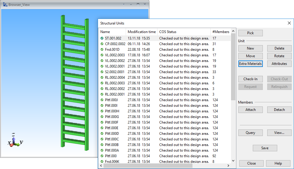
The Structural Units dialog opens listing the structural units of the model.
-
Select the new structural unit from the list, and then click Extra Materials.
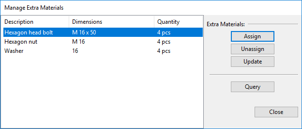
The Manage Extra Materials dialog opens listing the extra materials defined in the template configuration.
-
You can select an extra material and then click Update to edit its quantity or Unassign to delete it. You can add new materials by clicking Assign.
-
Close the extra material and structural unit management tools.
-
Result
The custom structural unit template is ready to be used in the project.
You can use CX export and import to copy templates between projects.
