P&ID Custom Labels
Labels are 2D decorations on the drawing sheet; they visualize information related to some PD object. The information that is shown in the label can be data extracted from the database, or the information can be simply visual, like a flow arrow on a pipe run. Even a label with data extracted from the database can be either a text or symbol type label.
The P&ID application allows creating script-coded labels defined in the Project Environment settings, in Resources > Scripts. Script-coded labels have the benefit of there being very few limitations to how you can customize them.
But, it is recommended that you use the pd label definitions described in Label Definitions whenever possible. This newer label definition type provides better performance when updating large diagrams, and to create them you do not need script coding. For more information, see Diagram label definitions.
Creating a New Label
Add a new label to the library.
Do the following:
- Create a new Diagram Object Template for the label.
- Add data string extraction to the labels script.
- Create a 2D symbol or new text type if needed.
- Add the label to the menu if you want to insert it also from the menu, and not only from the Selection Bar.
Creating a Diagram Object Template for the Label
Create a diagram object template for a label using the following information. For general instructions on making a Diagram Object Template, see Object templates.
Do the following:
-
Set the type of the template to Label.
-
Give a descriptive name for the label. The name is shown as description in the Selection Bar.
-
Select the symbol.
-
Symbol type: the name of the symbol.
-
Text type: the number of the text type written as textxx. Text types are defined for the example environment in textxx symbol (Document Production > 2D Symbols > PD > System > textxx).
-
-
Fill in or select values for attributes.
Attributes for label template
| PD labels search mask |
The object type selected from the diagram when inserting the label, e.g.
|
| PD label name | The name of the label/label type in labels script, for example ARMATURE_LABEL. |
| PD label type | Text or symbol type label. |
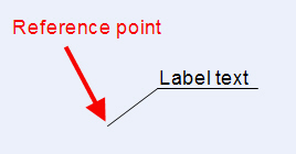
| PD label digit mode | Setting how the origin point of the label and the reference point are defined. If you can show the point yourself or if it is automatically defined according to the hit point. See the picture below. |
| Scale along x / y | Scale of the label. |
| Rotation | Default rotation of the label. |
Menu
You can add the label also to menu pd_label. Below is an example of the row in the menu.
val 1001;str Armature NS and PositionId;icn ;
    dat INSERT_LABEL("SYMBOLS","ARMATURE_LABEL","TEXT",DW_TXT_PNT_OG_RN,"26",1,1,0);;
| "SYMBOLS" | Search mask |
| "ARMATURE_LABEL" | Name of the label in labels script |
| "TEXT" | Type of the symbol, either "TEXT" or ""SYMBOL" |
| DW_TXT_PNT_OG_RN | Digitizing mode |
| "26" | If symbol type, the name of the symbol, if text type, the number of the text |
| 1 | Scale along x axis |
| 1 | Scale along y axis |
| 0 | Default rotation of the label |
Search mask
| "ANY" | Any object type |
| "SYMBOLS" | DG symbols |
| "CLINES" | DG connection lines |
| "POINTS" | DG (connection) points |
| "TEXTS" | DG texts |
| "LABELS" | DG labels |
| "GROUPS" | DG groups |
| "NO" | Free point |
Digitizing mode
| DW_TXT_PNT_OD_RN | Origin point given, no reference point |
| DW_TXT_PNT_OG_RN | Origin point digitized, no reference point |
| DW_TXT_PNT_OG_RD | Origin point digitized, reference point given |
| DW_TXT_PNT_OG_RG | Origin point digitized, reference point digitized |