Diagram label definitions
Tip: For information on label definitions for Plant Modeller or Piping Isometrics & Spools, see Label Definitions.
P&I diagrams can display labels that provide information about the objects shown in the diagram.
The labels are generated with configurable label definitions whose main constituents are the parametric 2D symbol that provides the label's graphical representation and the label text that can include information extracted from the COS or SQL database.
The project administrator prepares the required label definitions in the library or the project database. The label definition defines which diagram object types can use the given label, and what is shown as the label text. There are some predefined label definitions in the CADMATIC example project that can be used as templates for new ones.
Creating diagram label definitions
You can create a separate label definition for each label type that designers will be inserting into diagrams. You can create the label definition from scratch as described below, or you can make a copy of an existing label definition and use that as a template.
Prerequisites
-
Optionally, an icon that shows what an inserted label will look like. See Icons.
-
Optionally, a script that inserts specific information into the label.
Do the following:
-
Open the Project Environment dialog:
-
In the CADMATIC desktop, select Object > Library and Project Databases.
-
In the P&ID application, select File > Environment > All library and project.
-
-
Browse to [library or project] > Document Production > Label Definitions.
-
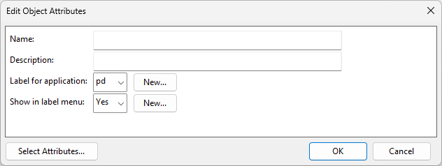
Select New > Label Definition. The Edit Object Attributes dialog opens.
-
Specify the attributes of the label definition:
-
Name – Enter a descriptive name for the label definition.
-
Description – Optionally, enter a more detailed description of the label definition and its intended use.
-
Label for application – Select 'pd' to specify that the label definition will be used in the P&ID application.
-
Show in label menu – Select whether to list this label definition when the user is selecting a label definition in the application.
Then click OK.
-
-
In the label definition list, double-click the label definition you just created. The Edit Diagram Label Definition dialog opens.
-
Define the Label definition settings and click OK.
-
Check in the label definition. If you created it in the library database, approve it for use in the project.
-
Add the new label definition to Labeling Styles that target the P&ID application and are approved for use in the project.
-
If you created the label definition via the P&ID application, restart the application and check that the label definition is now available in the Insert tool.

Label definition settings
The settings in the Edit Diagram Label Definition dialog define how the labels are to be generated.
Object attributes | Data | Script | Interaction at insertion | 2D Symbol settings | Object
Object attributes
These settings were first defined when creating the label definition, but you can also edit them here.
-
Name – Enter a descriptive name for the label definition.
-
Description – You can provide a more detailed description of the label and its intended use.
-
Use icon – Optionally, select this option and select the icon to display in the Label Definitions dialog. This is to help the diagram designer to select the correct label type.
Data
These settings define what kind of object the user must select to insert the label and what is the data to be shown in the label.
-
Search mask – Select what can be the target of the label:
-
DG symbols – The label can be attached to a diagram symbol to show information about that symbol.
-
DG connection lines – The label can be attached to a connection line to show information about that line.
-
DG symbols and connection lines – The label can be attached to a connection line to show information about that line and the connected diagram symbol.
-
DG connection node – The label can be attached to a connection node to show information about that node and the object that owns the node.
-
DG connection point – The label can be attached to a connection point to show information about the two diagram objects connected by that point.
-
-
Data Requests – Define data requests that first retrieve data from a column in the SQL database or from a COS attribute and then process the data for displaying in the label. If the whole label text is generated with a script, data requests are not needed.
-
Click Edit. The Combined Data Requests for Label Definition dialog opens.
-
To create a new data request, click Add, and define the request in the Edit Data Sources dialog.
-
When you have added all the data requests that are needed to build the label text, define the order in which the information is presented in the label. You can move a data request up or down in the list to change its position in the label.
-
When the data requests are ready and in the expected order, click OK.
-
Script
You can use a script to create or modify the label text. The script can retrieve additional information from the application, and then either append this information to the label text or completely replace the label text created by the data request. The label text produced by the script is passed to the 2D symbol and shown in the label.
-
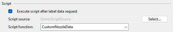
Execute script after label data request – Select this option to run a script after the label data request.
-
Script source – Click Select to browse for the script source.
-
Script function – Select the script function from the drop-down list.
In this example, we use a script to fetch various data from a node and the rating from the connected object. The label displays the node number, nominal size, node type, node name, and rating.
#include "include/dmutil.h"
#include "include/dbase.h"
#include "include/pd.h"
#include "include/dg.h"
#include "include/dw.h"
#include "include/cos.h"
#include "include/PdUtil.h"

/*This script fetches the rating information of a connected object to an equipment node.
If the connection is to an instrument, the information is fetched from the instrument bubble connected to the iline. */

CustomNozzleData(string data, handle parent_dg_obj, int nr_node)
{
    x = 0.0;
    y = 0.0;
    name = "";
    msg = "";
    ns = 0.0;
    q_ns = "";
    nbr = -1;
    fdir = -1;
    /* selected node to get the connected objects */
    if(PD_GET_NODE_INFO(parent_dg_obj, nr_node, name, ns, nbr, fdir) == 0) {
        S_PRINTF(q_ns, "%.0f", ns);

        con_point = DG_GETCPOINT(parent_dg_obj, nbr, x, y );
        con_objs = DG_GET_CONNECTED_OBJS_OF_CPOINT(con_point);
        n_objects = DM_VECTOR_SIZE(con_objs);
        if(n_objects > 0) {
            for(j=0; j<n_objects; j=j+1;) {
                con_dg_obj = DM_VECTOR_GET(con_objs,j);
                type = "";
                con_pd_obj = PD_GET_PDOBJ(con_dg_obj, type);
                pd_obj_id = PD_GET_OBJ_OBJECTID (con_pd_obj);
                if(type == "INSTRUMENT"|type =="INSTRUCTIONLINE"){
                        if(type == "INSTRUCTIONLINE"){
                            connected_instrument = query_instrument(con_dg_obj);
                            if(!ISINT(connected_instrument))
                                con_pd_obj= connected_instrument;
                                pd_obj_id = PD_GET_OBJ_OBJECTID (con_pd_obj);
                        }
                    rating = get_sql_data(pd_obj_id, "INSTRUMENTS");
                }
                if(type == "ARMATURE"|type == "PIPERUN")
                    rating = get_sql_data(pd_obj_id, "ARMATURES");
            }
        }
        DM_VECTOR_DELETE(con_objs);
        data = data + rating;
        return(data);
    }
}
get_sql_data(string oid, string table)
{
    is_null = 0;
    status = 0;
    pn = "";
    edit_mode = FALSE;
    arm_spec = "";
    if(table == "ARMATURES")
        arm_spec = "PdSpeckOid,";
    query = "SELECT "+table+".PdObjectId, TypeTbl, Pipeline,"+ arm_spec +"PIPELINES.PdSpeck1Oid FROM "+table+" LEFT OUTER JOIN PIPELINES ON "
    + table +".Pipeline = PIPELINES.PipelineId WHERE "+table+" .PdObjectId='"+oid+"' AND "+table+".Status<2";

    rec_set = DB_RS_OPEN(query, edit_mode);

        if (rec_set == 0 | (DB_RS_EOF(rec_set) & DB_RS_BOF(rec_set))){
            U_MESSAGE("Could not update data to Connections attribute");
            return (0);
        }
        else {
            while (!DB_RS_EOF(rec_set)) {
                pipeline = DB_RS_GET_FIELD(rec_set, "Pipeline", status, is_null);
                spec = DB_RS_GET_FIELD(rec_set, "PdSpecOid", status, is_null);
                if(ISINT(spec))
                    spec = "";
                spec1 = DB_RS_GET_FIELD(rec_set, "PdSpeck1Oid", status, is_null);
                subtbl = DB_RS_GET_FIELD(rec_set, "TypeTbl", status, is_null);
                if (table == "ARMATURES"){
                    pn = select_subtbl_data(table, oid, subtbl);
                    if(ISINT(pn))
                        pn = "";
                }
                if(pn == ""& spec == "" & spec1 != "")
                    pn = get_spec_rating(spec1);
                DB_RS_MOVE(rec_set, "NEXT");
            }
            DB_RS_CLOSE(rec_set);
        }
        return (pn);
}
select_subtbl_data(string table, string oid, string subtbl)
{
    q_pn = "";
    sel = pd_make_sql_query_by_posid(table, oid, PD_SQL_QUERY_EDITED);
    tbl = DB_TBL_OPEN_SQL_QUERY(table, sel);

    if(tbl == 0)
        return(0);
    st = 0;
    img = DB_FULL_IMAGE(tbl);
    rec = DB_NEXT_REC(tbl, img, st);

    if( !ISINT( rec )){
        val = DB_GET_FIELD(img,"PN",st);
        S_PRINTF(q_pn, "%.0f", val);
    }
    return(q_pn);
}
/* Function queries if iline is connected to an instrument bubble. Instrument pdobject
is returned to the array instead of iline for more detailed information. */
query_instrument(iline)
{
    con_objs = DG_GET_CONNECTED_OBJS_OF_OBJECT(iline);
    i_objects = DM_VECTOR_SIZE(con_objs);
    if (i_objects < 1)
        return(-1);
    for(i=0; i<i_objects; i=i+1;){
        con_dg_obj = DM_VECTOR_GET(con_objs, i);
        type = "";
        con_pd_obj = PD_GET_PDOBJ(con_dg_obj, type);
        if (type == "INSTRUMENT"){
            DM_VECTOR_DELETE(con_objs);
            return(con_pd_obj);
        }
    }
    DM_VECTOR_DELETE(con_objs);
    return(0);
}

get_spec_rating(string cos_id)
{
    COS_READ_OBJECT(cos_id);
    attrs = COS_GET_OBJECT_ATTRIBUTES(cos_id);
    pn= DM_GET_TAGVAL(attrs, "RT");

    DM_FREE_TAGREC(attrs);
    COS_FREE_OBJECT(cos_id);
    return(pn);
}
Using this example code, the Script function field is set to get additional text for the label from the 'CustomNozzleData' function.
Interaction at insertion
Select the appropriate Digit mode to define where the origin of the label is and whether a reference line is to be drawn.
-
Origin at the pick point. No reference line
-
User defines the origin. No reference line
-
User defines the origin. The reference line ends at the pick point
-
User defines the origin and the end of the reference line
2D Symbol settings
These settings specify the text style or graphical 2D symbol that the label is to use.
-
Type – Select whether the symbol is of type 'Text' (script-based text) or 'General' (a graphic symbol).
If Type=Text, define the following:
-
Name – Select the text style to use by clicking Browse or typing just the number of the text style, such as 18 for 'text18' (text in a box with reference line).
If Type=General, define the following:
-
Name – Select the graphical 2D symbol to use by clicking Browse or typing the name of the symbol.
-
Scaling [pm] – Specifies whether scaling is inherited from the current view or defined by user. If defined by the user, specify scaling and rotation as described below.
-
Scale X, Scale Y – These specify the scale factors of the symbol in X and Y direction. The default scale 1.0 indicates that symbol units are the same as sheet units.
-
Rotation – Specifies the rotation angle of the symbol.
The project administrator can define new text styles and graphical 2D symbols in Project Environment > [library or project] > Document Production > 2D Symbols.
Object
Click Attributes if you want to add or remove attributes.
Edit Data Sources
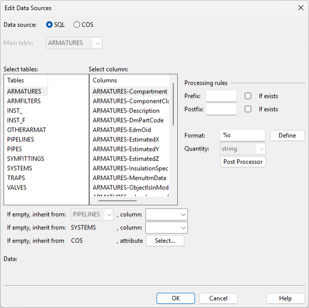
In the Edit Data Sources dialog, define from where the data request is to retrieve data for the label text.
Do the following:
-
Data source – Select whether to get the data from the SQL or the COS database.
-
If you chose SQL as the data source, define the following settings.
 Show/hide details
-
Main table – Select the required main table from the drop-down menu.
-
Select tables – Select the required table from the list.
-
Select columns – Select the required main table or sub-table column from the list.
Note: If the column belongs to a main table, the data request works for all objects that use this main table. For example, 'EQUIPMENTS-PosId' works for all kinds of equipment: vessels, pumps, heat exchangers, and so on.
If the column belongs to a sub-table, the data request only works for objects that use this sub-table. For example, 'PUMPS-Power' only works with pumps. However, the label definition can support multiple object types if you define a separate data request for each applicable sub-table. -
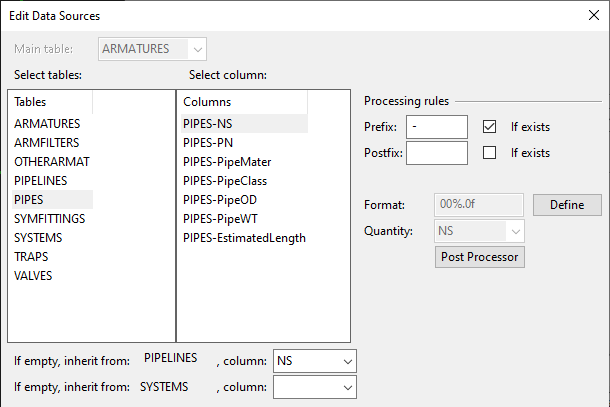
You can set the data request to inherit the value when it is not available in the selected column.
-
If empty, inherit from [table] – Select the table and column from which to inherit the value.
-
If empty, inherit from SYSTEMS – Select the SYSTEMS table column from which to inherit the value.
-
If empty, inherit from COS – Select the COS attribute from which to inherit the value.
See Pipeline label that inherits data from pipeline and system.
-
-
-
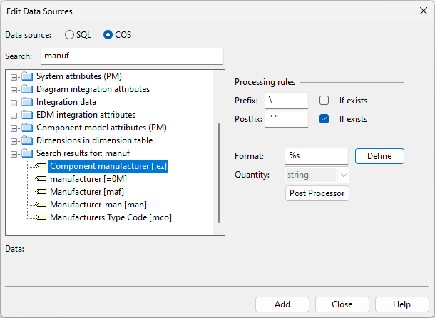
If you chose COS as the data source, select the COS attribute whose value you want to retrieve.
-
Define the processing rules:
Show/hide details
-
Prefix, Postfix – You can add line breaks to a label by specifying the backward slash character '\' as a prefix. You can separate text strings with a space by adding " " as a prefix or postfix.
-
If exists – Select this option to prevent unnecessary formatting when there is nothing to retrieve in the specified column.
-
Format – The Define button opens the Select Quantity Format dialog where you can define how to format the retrieved data.
-
Format string – See Format strings for more details.
-
Length type – If the data request relates to a length value, select 'General decimal format' and define the exact format settings manually, or select 'Foot/inch fraction format' and select the format from the Format drop-down menu. If this option is dimmed, for example when the data request relates to a pressure value, you must specify the format settings manually.
-
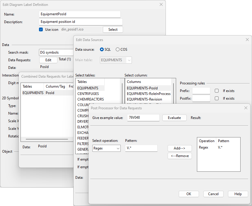
Post Processor – This button opens the Post Processor for Data Requests dialog where you can specify one or more operations that will modify the value received by the data request.
-
Give example value – Enter an example value and click Evaluate to test your post processor settings.
-
Select operation, Pattern – Select the type of operation to perform and the pattern to use:
-
Head – Pattern defines how many characters to keep from the start of the value.
Example: With pattern 3 the value '123C456' becomes '123'. -
Search – Keep the end of the value, starting from the characters defined in the pattern.
Example: With pattern ABC the value '123C456' becomes 'C456'. -
Stringterm – Remove the end of the value, starting from the characters defined in the pattern.
Example: With pattern ABC the value '123C456' becomes '123'. -
Substring – Pattern defines how many characters to remove from the start of the value.
Example: With pattern 3 the value '123C456' becomes 'C456'. -
Tail – Pattern defines how many characters to keep from the end of the value.
Example: With pattern 3 the value '123C456' becomes '456'. -
Regex – Pattern defines a regular expression for the characters to keep/remove.
Example: With pattern [ABC].* the value '123C456' becomes 'C456'.
Note: If you specify multiple operations, they are executed from top to bottom. In the example below, with the Regex operation the value '123C456' becomes 'C456', but then the Substring operation removes the first character, and the result is '456'.
-
-
-
-
-
Click Add.


Example label definitions
Here are some examples of diagram label definitions.
Position ID label with additional data
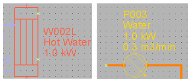
In the CADMATIC example project, the 'EquPosIdData' label definition can be used to insert multi-line labels to, for example, heat exchangers and water pumps, as shown below.
-
First and second row show 'PosId'and 'Medium' from the EQUIPMENTS table.
-
Additional rows show object-specific technical data:
-
A heat exchanger label shows 'PowerOfExchange' from the EXCHANGERS table.
-
A pump label shows 'Power' and 'Capacity' from the PUMPS table.
-
A vessel shows 'Volume' from the VESSELS table.
-
A water column shows 'NumOfTrays' from the COLUMNS table.
-
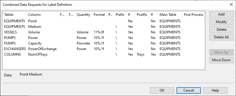
Note: This label will only work for object templates that use the VESSELS, PUMPS, EXCHANGERS or COLUMNS sub-tables, because those sub-tables are included in the data requests.
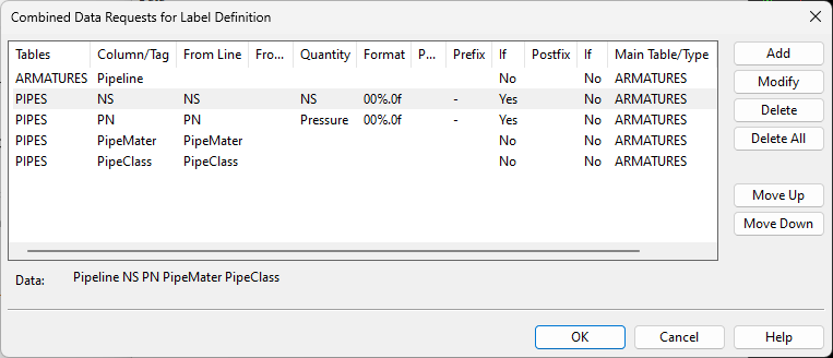
Pipeline label that inherits data from pipeline and system
In the CADMATIC example project, the 'Pipline1' label definition can be used to insert pipeline labels that inherit their data from the Pipeline and the System.
For pipe runs and valves, it is a common practice that the diagram designer only defines the nominal size or the materials to parts that are different from the default values given to the pipeline. To show this data in labels, first you want to search, for example, the PIPES or the ARMATURES table, and if there is no data, then from the PIPELINES table. It is useful to have a label definition that automatically inherits these values.
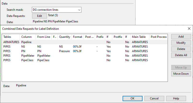
In this label definition, 'NS', 'PN', 'PipeMater', and 'PipeClass' are shown from the pipe run if it has the data. If the pipe run does not have the data, then the data is shown from the pipeline.
In the label definition, inheritance is defined in the If empty, inherit from fields. The data type of the tables that are involved in inheritance must be the same: if the PIPES table is searched for a float-type value, then also the PIPELINES table must be searched for a float-type value.
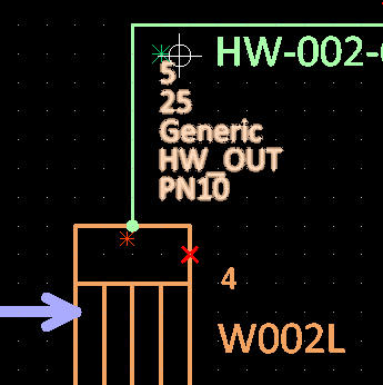
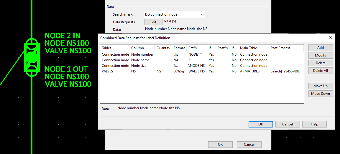
Connection node label
The properties of a connection node, such as node name, flow direction and nominal size, can be shown in a label that is attached to the connection node in a drawing.
When creating a diagram label definition for connection nodes, make sure you do the following:
-
Set the target (search mask) to 'DG connection node'.
-
Create data requests to the 'Connection node' table.
In addition to retrieving and showing properties that belong to the node itself, a node connection label can also show properties that belong to the object that owns the connection node.
The example below shows a multi-line label definition (Text Type = 39) that generates labels that have three data rows.
-
First row shows node number and node name, which it gets from the 'Connection node' table.
-
Second row shows node's nominal size, again from the 'Connection node' table.
-
Third row shows the nominal size of the valve that contains the node, and this data comes from the ARMATURES -> VALVES table.
The label definition uses prefixes that add text (NODE, NS, VALVE) and spaces (using quotation marks " ") as well as create line breaks (using the backward slash '\' character).