Managing pipelines
In CADMATIC P&ID and Plant Modeller, you can manage pipelines by selecting File > Environment > Systems and Lines.
Tip: You can also manage pipelines via File > Environment > All Library and Project > [project] > Pipelines. New pipelines can be created via the Model Tree pane, as described in Managing tree items.
Creating a new pipeline
Do the following:
-
Select File > Environment > Systems and Lines. The Systems & Lines object browser opens.
-
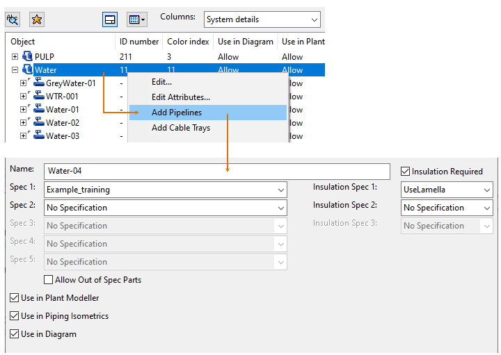
Right-click the System where you want the new pipeline to be created, and select Add Pipelines.
-
Specify the pipeline details:
-
Enter a name for the pipeline. The maximum length is 100 characters.
Note: If the pipeline is to be used in the P&ID application, the name cannot be the same as the name of its System.
-
Select one or more piping specifications for the pipeline, as appropriate. The maximum is five different piping specifications.
-
Select the option Allow Out of Spec Parts if also piping parts that are not included in the specifications can be used.
-
Select the option Insulation Required if having insulation is mandatory in this pipeline.
-
Select one or more insulation specifications for the pipeline, as appropriate.
-
Select the option Use in Plant Modeller to make the pipeline visible in the Plant Modeller application.
-
Select the option Use in Piping Isometrics to make the pipeline visible in the Piping Isometrics & Spools application.
-
Select the option Use in Diagram to make the pipeline visible in the P&ID application.
-
- If you want to add object attributes to the pipeline, click Attributes.
-
Click Add to create the pipeline.
-
When you have added all the required pipelines, click Close.
We recommend to define and design pipelines as follows:
- Pipeline has only one piping specification and insulation specification.
- Pipeline has one clear starting point and one end point.
- Pipeline is continuous and the design properties are the same throughout the pipeline.
- The mass flow of flow media is constant throughout the pipeline.
- There are only branches without remarkable continuous mass flow like sample takings, air removals, flushing, drain.
Editing diagram attributes
When you open the Systems & Lines dialog using either CADMATIC P&ID or Plant Modeller that is using P&ID integration, you can edit the values of pipeline attributes that are stored in the SQL database.
Prerequisites
- Optionally, add the columns of the attributes you intend to edit to the Systems & Lines dialog, so that you can easily see the attribute values before and after the change. See Object browser columns.
Do the following:
-
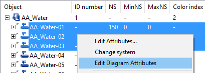
In the Systems & Lines dialog, select the pipeline or pipelines whose P&ID attribute values you want to edit.
-
Right-click the selection and select Edit Diagram Attributes.
-
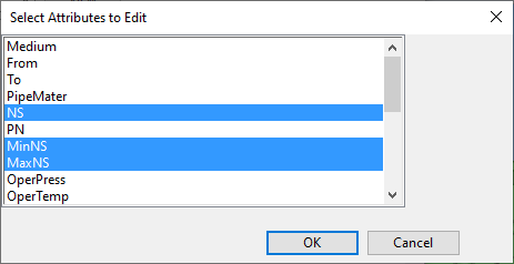
If you are editing a single pipeline, the Select Attributes to Edit dialog opens. Select which attributes you want to edit, and click OK.
-
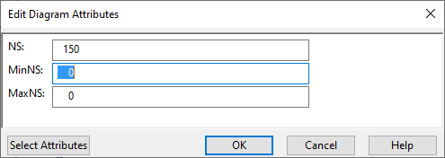
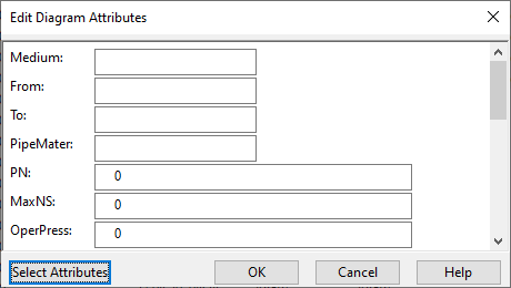
The Edit Diagram Attributes dialog opens, and its content depends on whether you are editing a single pipeline or multiple pipelines.
-
If editing a single pipeline, the dialog lists only those attributes that you selected in the previous step.
Click Select Attributes if you want to add more attributes to the list.
-
If editing multiple pipelines, the dialog lists all those attributes that have exactly the same value in the selected pipelines.
Click Select Attributes if you also want to set a single value to an attribute that currently has several different values in the selected pipelines.
Note: An attribute whose value is not the same in all the selected pipelines displays an empty value field until you enter a value in it.
-
-
Enter the new values, and click OK.
The modified values are stored in the SQL database and displayed in the object browser if the related columns are visible.