Insert tab
The Insert tab of CADMATIC Viewer contains the following tools.
2D Symbol Editor Options
These options are available when editing 2D symbols.
-
Layer – If selected, the user can change the layer of each entity from the Layer drop-down menu, and layer information is saved in the symbol file.
-
Color – If selected, the user can change the color of the selected entities from the Color drop-down menu, and color information is saved in the symbol file.
-
Lineweight – If selected, the user can change the line weight of the selected entities from the Lineweight drop-down menu, and line weight information is saved in the symbol file.
Note: You might want to enable color and line weight for example when editing a company logo. You should not enable them when editing a symbol which is used as a diagram object template, because these properties should be adopted from the System in the actual diagram.
-
Axis – If selected, the lines of the main axes are displayed in the drawing area.
Node Options
These options are available when editing 2D symbols used in the P&ID application.
- Flow direction – Allows setting the flow direction of the selected nodes to In/Out, In, or Out.
- Node type – Allow selecting the node type: Generic, Piping, Instrument or Electric.
- Set node name – If selected, inserting a new node prompts the user to enter a name for the node.
Node Direction
These options are available when editing 2D symbols used in the P&ID application.
-
Select what should be the node direction for new nodes: 0 (right), 180 (left), 90 (up), 270 (down), or freely defined by the user.

Nodes
These options are available when editing 2D symbols used in the P&ID application.
-
Node – Inserts a new node.
- If the Set node name option is enabled, the user is prompted to enter a name for the node.
- If node direction is free, the user is prompted to define the node direction.
Draw
You can use drawing tools to add text, lines, dimensions and hatching patterns.
-
Text – Allows inserting text into the drawing. This can be a static text string or remote text stored in a text file.
-
Line – Allows drawing different types of lines.
-
Arc – Allows drawing arcs, circles, and ellipses.
-
Dimension – Allows inserting dimension annotations to the drawing.
-
Leader – Allows inserting a text annotation as a leader or multileader object. Leader's style is defined when inserting the leader, whereas multileaders use the Multileader Style settings defined on the Style tab—see Multileader style.
-
Hatch – Allows filling an object or area with a hatching pattern. If editing a 2D symbol, note that hatches will automatically be converted to lines when the symbol is compiled into binary format.


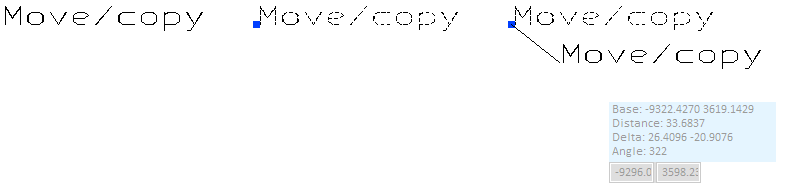
After inserting a drawing object, you can move it by its grip points. Click the object to display its grip points, and then click the grip point you want to move; if the object has just one grip point, the whole object will be moved. Then, select the target location, either by clicking or by pressing Tab and typing the X and Y coordinates in the on-screen fields. If you select the target location by clicking, holding down Ctrl while clicking copies the object to the target location instead of moving it there.
Block
-
Block – Allows inserting blocks into the drawing.
-
Attribute Definition – Allows inserting attribute definitions into the drawing. The Add Attribute Definition dialog opens for specifying the attribute definition properties.
-
Reference drawing – Allows inserting a DWG or DXF as a reference drawing. After selecting the file to insert, the Attach Reference Drawing dialog opens for defining the insertion settings.
-
Table – Allows inserting a table into the drawing. Define the table properties in the property pane.


Create
- Create region – Transforms the selected, closed loop of drawing objects into a region.
- Create polyline – Transforms the selected drawing object into a polyline.
External
-
Image – Opens the Insert Image dialog for inserting an external image file into the current drawing.
Note: 2D Symbols cannot include imported images.
-
OLE Document – Opens the Insert OLE Document dialog for inserting an external OLE document into the current drawing.
-
Drawing file – Allows inserting a DWG or DXF file into the current drawing. The user is prompted to select whether the inserted objects should keep their properties or use the common object properties of the target drawing.
-
Drawing file as block – Allows inserting a DWG or DXF file as a block into the current drawing. The user is prompted to define the block name.
-
PDF File – Opens the Import PDF Document dialog for inserting a PDF file into the current drawing.
-
Underlay – Allows inserting a PDF, DWF, or DGN file as an underlay to the current drawing. An underlay does not become a part of the drawing, but the objects in the drawing can reference the entities in the underlay. The Import PDF/DWF/DGN Underlay Document dialog opens for defining the import settings.


Other
-
Viewport – Allows inserting viewports into a page layout. This requires that a layout other than "Model" has been selected from Layout on the Home tab—see Miscellaneous.
