Home tab
The Home tab of CADMATIC Viewer contains the following tools.
Layers
-
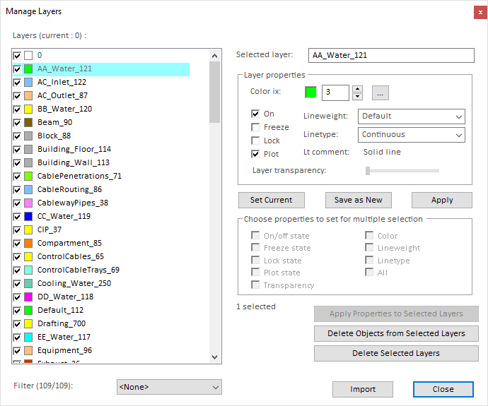
 – Opens the Manage Layers dialog.
 -
 – Sets the selected object's layer to be the current layer.
 -
 – Freezes the layer of the selected object.
 -
 – Turns off (hides) the layer of the selected object.
 -
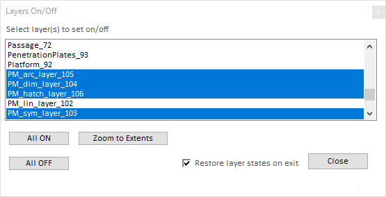
 – Opens the Layers On/Off dialog for selecting which layers to show.
Zoom/pan
-
 – Zoom in.
 -
 – Zoom out.
 -
 – Enables panning. To pan, hold down the left mouse button and drag.
Alternative panning methods:
- Hold down P and the left mouse button, and drag.
- Hold down the middle mouse button and drag.
-
 – Zooms to the extents (bounding box) of the objects in the drawing.
 -
 – Zooms to a rectangle defined by two points the user picks from the drawing.
Common tools
-
 – Undo the last action.
 -
 – Redo the last action.
 -
 – Shows the properties of the selected object.
 -
 – Allows moving the selected objects. You can select several objects by holding down Shift when clicking, or by holding down the left mouse button and drawing a rectangle around the objects. Then, select the base point and the target location, either by clicking or by pressing Tab and typing the X and Y coordinates in the on-screen fields. If you select the target location by clicking, holding down Ctrl while clicking copies the objects to the target location instead of moving them there.
-
 – Allows measuring the distance between two points.
 -
 – Cuts the selected object. After selecting the object, pick the reference point to use for pasting the object.
 -
 – Copies the selected object.
 -
 – Pastes the copied object to the specified reference point. Press Esc to exit the tool.
 -
 – Deletes the selected object.
 -
 – Lists the properties of the selected object in a text file.
Miscellaneous
- Refresh – Refreshes the drawing graphics.
- Palette – Allows setting the background color of the drawing area to Black, White, Default, or Other.
- Options – Opens the Options dialog. See The Options dialog.
- Console – Displays a console pane at the bottom of the application window. In the console you can use AutoCAD® System Variables supported by the DWG version of the current drawing.
- Database content – Displays the database content of the current drawing.
- Layout – Allows selecting which layout to use. Layouts can be managed as described in Manage.
Ortho/tracking
- Ortho (F8) – If selected, lines can be drawn only in horizontal or vertical direction. Otherwise, lines can be drawn in any direction.
- Object tracking (F11) – Allows selecting a drawing reference point from any object.
In this example, orthogonal locking and object tracking are enabled. The user specifies the end point of a horizontal line segment by picking a reference point from a different object.
![]()
Polar tracking
-
Polar (F9) – If selected, lines can easily be drawn at a specific angle. When the reference line (polar axis) is at the angle specified in "Polar angle", the reference line extends over the entire drawing area, instead of stopping at the point of the cursor.
-
Polar angle – Specifies the angle to use in polar tracking.
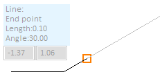
In this example, polar tracking is enabled and polar angle is set to 30°. The user first draws a horizontal line segment and then changes the direction, and polar tracking indicates when the line is at a 30° angle.

Object snapping
- Object snap (F3) – If selected, the cursor snaps to objects as defined in the settings.
- Settings – Allows selecting how to snap to objects: end, middle, near, center, tangent, perpendicular, intersection.
Grid
- Grid (F7) – If selected, the drawing area displays grid points.
- Grid snap – If selected, the cursor snaps to grid points. Snapping works even if the grid points are not displayed—when snapping to a grid point, there is a highlighted rectangle next to the cursor:

- Settings – Opens the Grid tab of the Options dialog. See Grid.

