Cable Routing
In the Cable Manager dialog, on the General tab, the Cable Routing section contains tools for routing cables.
Using the cable router requires that you have created the nodal network and saved the resulting cable network parts to COS. The nodal network might also need to be recreated if the 3D model changes and the cable network parts no longer match the cable ways in the model. Each user organization must decide when should the nodal network be recreated. For more information, see Nodal Network.
Tip: You can add "Cable routed by" (.GJ) to the columns of the cable list to see who has routed a specific cable and when.
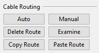
Auto
You can use automatic routing to let the program find the shortest route for the cables. You can use this to route a cable for the first time as well as to re-route cables that already have a route, especially after the cable routing network has been re-generated.
Do the following:
-
In the Cables section of Cable Manager, select the cables to be routed.
-
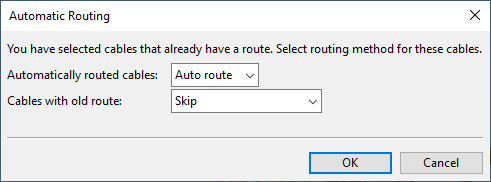
In the Cable Routing section, click Auto. The Automatic Routing dialog opens, listing options that are applicable to the cables you have selected.
-
Select how to proceed:
-
Automatically routed cables – Select what to do to cables that currently have an automatically defined route:
-
Auto route – Find the shortest route in the current network, using automatic routing.
-
Skip – Ignore cables that have an automatically defined route.
-
-
Manually routed cables – Select what to do to cables that currently have a manually defined route:
-
Auto route – Find the shortest route in the current network, using automatic routing.
-
Re-route – Find the shortest route in the current network, using manually selected nodes.
-
Skip – Ignore cables that have a manually defined route.
-
-
Cables with old route – Select what to do to cables that once had an automatically or manually defined route, but then the network was recreated and now only the coordinates of the old route remain:
-
Skip – Ignore cables that have an old route.
-
Try to restore old route – Try to restore the old route.
Tip: This can be used, for example, when a good route has become unusable and you are trying to make it usable again by modifying the network. Run the tool with this option to see if the modified network allows the old route to be restored.
-
-
Not routed cables – Select what to do to cables that currently do not have a route:
-
Auto route – Find the shortest route in the current network, using automatic routing.
-
Skip – Ignore cables that are not routed.
-
-
-
Click OK.
-
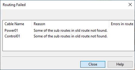
If there are problems, you are prompted whether to browse the failed cables. If you select Yes, the Routing Failed dialog opens, listing the problematic cables and information about them.
If a cable is indicated to have Errors in route, you can do the following:
-
You can accept the route anyway if you right-click the cable and select Accept Route.
-
You can investigate the errors if you right-click the cable and select Show error location.
-
Below you can find more information about various aspects of automatic routing.
Air Jumps in Auto-Routing
The automatic routing decides whether to allow a cable to jump from one cable tray to another. These so-called air jumps are considered to be "more expensive" than routes that go via continuous cable ways, and therefore routes that involve air jumps are avoided if there is an almost equal route that does not contain Cable route air jumps.
Head/Tail Jumps in Auto-Routing
From head or tail equipment, cables usually jump to a node in the nearest cable way. In some cases, cables can go directly from one equipment to another without going via any of the cable ways. Creating of head/tail jumps is also affected by the equipment being located inside a compartment, as described below.
If head and/or tail equipment is inside a compartment:
-
There is no collision checking for head/tail jumps because the program adds some extra length that allows the cable to be routed within that defined space.
-
The target node must be located in the same compartment as the head/tail object. This ensures that air jumps do not pass through bulkheads or decks that separate compartments.
-
Cables can jump directly from one equipment to another if both are in the same compartment and the distance between them does not exceed the value of Max direct jump between head and tail objects in Cable Router Setup.
If head and/or tail equipment is not inside a compartment:
-
There is collision checking for head/tail jumps. Objects that should be ignored can be defined with Objects ignored at head/tail jumps in Cable Router Setup.
-
The distance to the target node must be shorter than the value of Max auto-routed head/tail jump if equipment is not in compartment in Cable Router Setup.
-
Cables can jump directly from one equipment to the other if neither is in a compartment and the distance between them does not exceed the Max auto-routed head/tail jump if equipment is not in compartment and Max direct jump between head and tail objects values in Cable Router Setup.
Note: You can override these rules by using manual routing.
Interference Class Segregation in Auto-Routing
Automatic routing takes into account the interference classes of the cables.
Cables can have an interference class such as High Voltage, Power, or Bus. Cables that belong to different interference classes must not be placed too close to each other. The minimum distance between different interference classes is called segregation distance. For example, if there must be a 50 mm gap between a power cable and a bus cable, the segregation distance between the Power interference class and the Bus interference class is 50 mm.
Segregation is only considered for cables that are placed in the same cable tray part. When searching for the shortest route for a cable, the cable router first checks whether the target cable tray allows the interference class of the cable and then checks whether the segregation requirement leaves enough space for the cable.
The interference classes and segregation distances are defined in Cable Router Setup.
Manual
In the Cable Routing section, clicking Manual opens the Manual Cable Routing dialog where you can pick routing nodes manually. It also displays the texts 'Head' and 'Tail' in their respective locations within the work views. The cable node to use as the start or end node must have a node ID. You can add node IDs via Modify or Node IDs.
Using manual routing, you can make selections that auto-routing does not make:
-
Manual routing does not check for maximum air jump length from a node to a head or tail equipment that is not in a compartment.
-
Manual routing accepts a route from a node to a head or tail equipment that is not in the same compartment.
-
Manual routing does not check whether the route between a node and a head or tail equipment is clear from other objects.
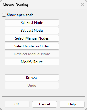
The Manual Cable Routing dialog contains these commands:
-
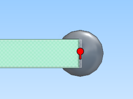
Show open ends – Select this option to display a red icon on top of all cable nodes that have only one valid segment or are not connected at all.
Clear the option to remove the icons.
-
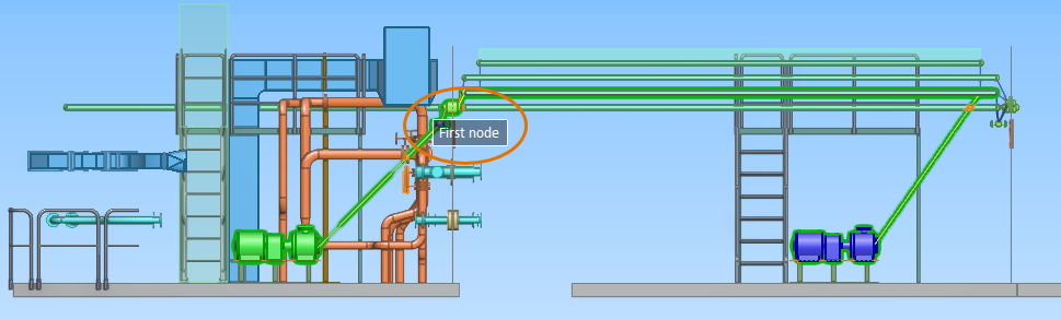
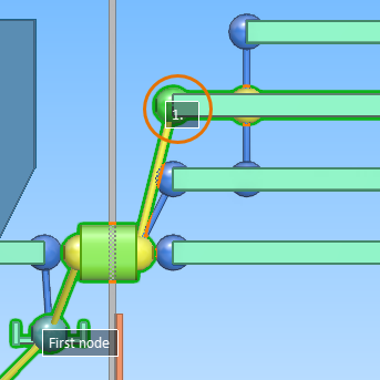
Set First Node – Allows selecting the cable node that connects the cable to the head equipment. The node to select must have a node ID. Selecting the node displays the label 'First node' in the work view, and the name of the button changes to Remove First Node, allowing you to remove the first node if needed.
-
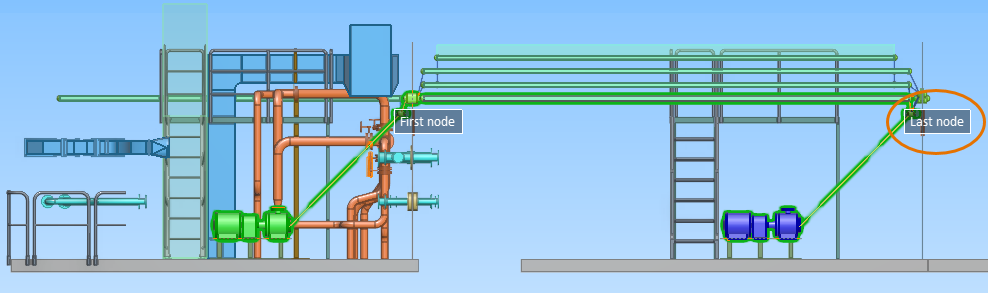
Set Last Node – Allows selecting the cable node that connects the cable to the tail equipment. The node to select must have a node ID. Selecting the node displays the label 'Last node' in the work view, and the name of the button changes to Remove Last Node, allowing you to remove the last node if needed.
-
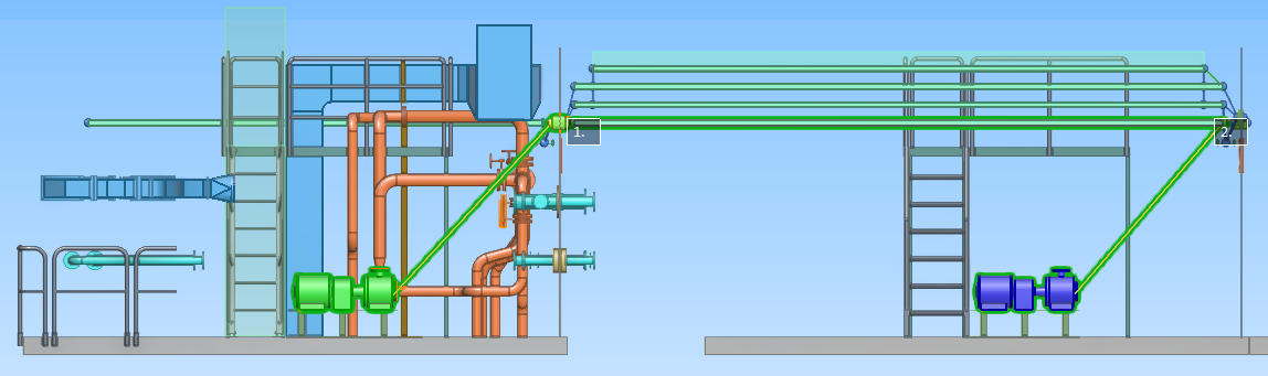
Select Manual Nodes – Allows defining a specific route for the cable by selecting any number of nodes that should be used in the route, in any order. That is, you do not need to pick all the nodes, and the picking order does not affect the routing order. Starting this command clears any previous selections except the first and the last node.
When you have picked the nodes you want to use and press Enter, the program performs automatic routing to generate the segments before, between, and after the picked nodes. Each node that you manually assign with this tool is given an ordinal number. While the program is searching for the best route, you can choose to interrupt the operation if it is taking too much time.
You can modify the generated order with the Modify Route tool.
-
Select Nodes in Order – Allows selecting a set of nodes in sequential order from the head to the tail. Starting this command clears any previous selections except the first and the last node. Pressing Enter accepts the set and auto-routes the cable.
-
Deselect Manual Node – Allows removing a manually selected node, but not the first or the last node, from the route. Pick the node that you want to remove and evaluate the new route that is shown in the views. Press Enter to confirm the removal.
-
Modify Route – Allows modifying the current route by routing the cable via nodes that it did not use previously. Each node that you manually assign with this tool gets an ordinal number that designates the position of the node along the route.
The tool always shows in green the nodes that you can select at the given moment.
-
 You can move the 'first node' or 'last node' assignment to a different node:
- Select the currently used first/last node and press Enter.
- Select the node that should become the first/last node and press Enter.
-
You can set the cable to go via specific nodes:
-
Select a node that is used in the route. If the route already contains manually selected nodes that have an ordinal number, selecting an automatically defined node assigns an ordinal number to that node, and the other nodes are re-numbered accordingly. You can try selecting different nodes to see how it changes the order.
When the node that you want to re-assign is selected, press Enter. Now all the nodes that are not used in the route currently are displayed in green to indicate that they are possible routing points.
-
Select the node to which the cable should be routed. The applicable ordinal number is assigned to that node. You can try selecting different target nodes to see how it changes the routing. The program immediately prompts you if it cannot complete the route via the selected node.
When the node that you want to use is selected, press Enter. The manual routing dialog displays again.
-
Select Modify Route if you want to modify another node.
This way, you can route the cable via a specific route, changing the route node by node. The ordinal numbers are stored in the cable, so you can return to modify the route also later, if needed.
-
-
-
Browse – Allows browsing the 3D model. Press Esc to return to the dialog.
-
Undo – Undoes the latest action. Note that there is no Redo command in this context.
-
OK – Accepts the currently defined route.
-
Cancel – Cancels the modifications.

Delete Route
Select one or more cable routes and click Delete in the Cable Routing section to delete those routes.
Examine
You can examine cables whose route is currently displayed as either "changed" or "broken", to try to identify what has caused the assignment into these categories. This could be due to, for example, a cable way having been moved or deleted. In the case of a changed route, you can use the examination tool to accept the new route.
Do the following:
-
In the Cable Manager dialog, browse to the required category: Cables > Route Changed or Cables > Route Broken.
-
Select the cables you want to examine, and click Examine. The following happens:
-
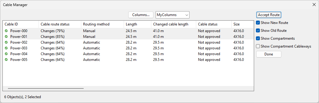
The Cable Manager dialog is adjusted to show only the cables you selected and commands and options that are relevant to the examination of the cable routes.
-
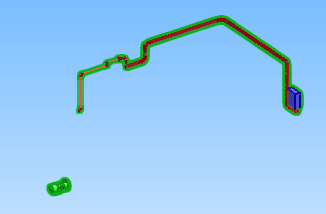
The Cable View opens. This is a shaded view that shows the old and new routes in different colors and highlights the issues in the changed/broken routes with overlay icons (exclamation mark symbol). Overlay icons are also displayed for overfull segments (percentage symbol) and disabled objects ("no entry" symbol).
Show/hide details
In the cable view, the cable network parts and their host objects are color-coded:
-
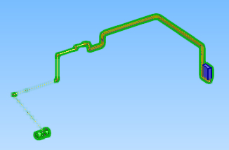
Yellow for the old route.
-
Red for the new route.
-
Brown where the old and new routes coincide.
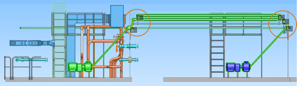
In this example, the old and new routes partly match (brown), but due to some cable trays having been moved, parts of the old route (yellow) do not align with the new route (red):
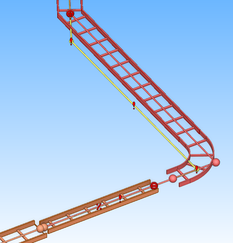
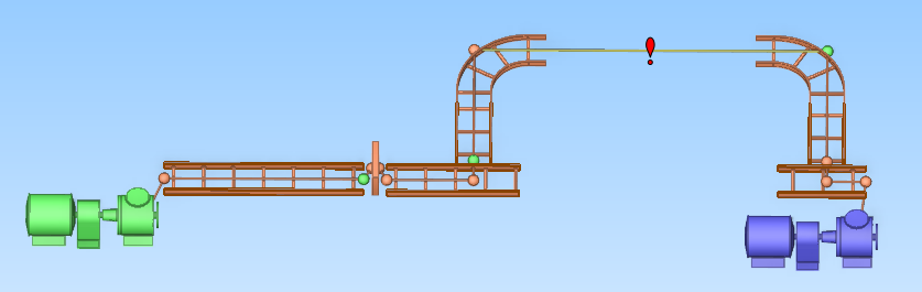
In this example, the old and new routes fully match (brown), but the deletion of a cable tray has broken the route:
-
-
-
You can examine the routes visually.
-
Show New Route – Select this option to show the new route in the shaded view.
-
Show Old Route – Select this option to show the old route in the shaded view.
-
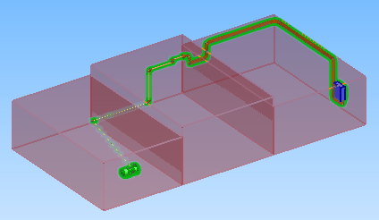
Show Compartments – Select this option to show the compartments along the route in the shaded view.
-
Show Compartment Cableways – Select this option to show also the cable ways that are not used in the route in the shaded view.
-
-
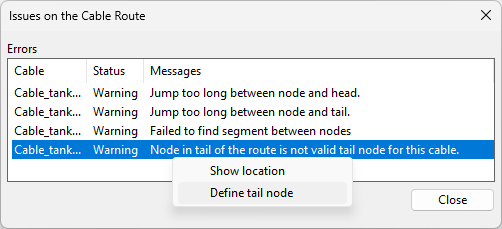
For broken routes, you can run the Inspect Route tool. When the tool lists the issues it found, you can select an issue from the list, and open the context menu to see what can be done with it. Most issues enable you to at least see their location in the 3D model. The following issues can also be fixed if the cable is checked out:
-
Missing pull marker.
-
Missing head or tail node. The head or tail node of the route may be missing if the corresponding node has disappeared from the model and there is no suitable node at the same location. In this case, the user can specify which node to use as the head or tail node, and the cable router will try to find the route to the next valid corner node.
-
-
You can accept the changed routes of specified cables by selecting the cables and clicking Accept Route. (This command is not available for broken routes.)
-
If accepting several cable routes at the same time and there are some issues in those routes, you are prompted whether to really accept them.
-
If accepting a single route and there are some issues, those issues are listed and you can click an issue to see its location in the route.
-
-
Click Done. The Cable Manager dialog returns to its normal state.

Copy Route
In the Cable Routing section, you can use the Copy Route tool to copy the route of the currently selected cable to the clipboard.
You can only copy a single cable at a time, the status of the cable must be "Ok", and the route cannot be a direct route from one equipment to another.
Paste Route
In the Cable Routing section, you can use the Paste Route tool to paste a copied route to one or several selected cables.
The program validates the route for each target cable. If the route is possible for some of the cables but not for all of them, the program shows why it is not possible and you can choose whether to continue (copy the route to those cables where it is acceptable) or cancel the operation.
Note: Pasting enables long air jumps and air jumps between compartments.