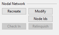
Nodal Network
In the Cable Manager dialog, on the Tools tab, the Nodal Network section has tools for managing the cable routing network of the 3D model. This network is composed of nodes and segments, and each segment represents a potential route for one or more cables.
While it is possible to add and remove nodes and segments manually, it is easier to use a tool that automatically generates a comprehensive cable routing network. This tool inserts nodes and segments in all suitable locations, based on the cable ways (including cable trays, cable pipes, and cable penetrations) that are defined in the 3D model. Segments have a maximum length of 8 meters, and if a straight cable tray piece is longer than this, the program adds additional nodes between the end nodes.
Recreate
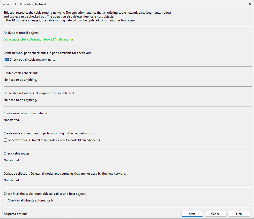
In the Nodal Network section, the Recreate button opens the Recreate Cable Routing Network dialog. This tool, which can be run anytime but only by one user at a time, uses the cable way runs in the 3D model to generate a network of nodes and segments that can then be used for routing cables.
The nodes and segments, whose COS object type is 'Cable Network Part', are visible in the 3D model while you are using the cable router, and also at other times if 'Cable router items' is set as active in Inactivity filter.
The cable routes that go via the nodes and segments are stored in COS. If the cable routing network is recreated, the existing cable routes may still be valid also in the new network, or they can be reported as being broken or containing a given percentage of changes. You can set the cable router to highlight the differences between the cable routing network and the 3D model, as described in Overlays.
If the model contains user-defined nodes whose cable tray has been moved or deleted, the recreate tool does the following:
-
User-defined nodes stay in their original location if there is a segment (original or new) also in the new network.
-
User-defined nodes are moved with the cable tray if there is no segment in the original location in the new network.
-
User-defined nodes whose cable tray has been deleted remain as a node in the air, and there is a warning about this in the cable network build log.
Before running the tool, consider whether to save the new network immediately or later:
-
If you run the tool but do not allow it to check in the new cable network parts, you can still undo (and redo) the operation in the Plant Modeller main window.
-
If you run the tool and allow it to check in the new cable network parts (or check them in yourself), the changes are permanent and cable routing starts to use the new network.
-
If you run the tool, save the new network, and then later the cable ways are changed, you might need to run the tool again to generate a new network and update the cable routes.
Conversion mode
3D models that have been created before the 'Cable Network Part' object type was introduced in version 2021T3 must first be converted to use the new network. If you upgrade from an earlier software version and conversion is required, the cable router opens the Recreate… dialog with some options specific to the conversion. When running this tool in conversion mode, the old nodes, segments, and routed cables must be checked out so that they can be modified; otherwise, many routes might become broken in the process.
Before opening cable manager and running the tool, you can use the Project Environment dialog to add 3D Spaces to your "objects ignored at air jumps" query. This will prevent 3D Spaces from blocking cable routes in the new cable routing network.
After the conversion, the Recreate… dialog only shows options for the normal mode where the network is updated without needing to check out or modify any model objects.
Prerequisites
-
Before opening the Cable Manager dialog:
-
We recommend that you save any unsaved changes in the 3D model. (Be aware that after recreating the cable routing network, checking in the new network will automatically save all changes.)
-
If you are using Sister Project Management, review the information in Sister projects and cable router.
-
-
In the Cable Manager dialog:
-
Review the Network section of cable router settings and make changes if needed. For example, add 3D Spaces to your "objects ignored at air jumps" query.
-
Do the following:
-
On the Tools tab, in the Nodal Network section, click Recreate. The Recreate Cable Routing Network dialog opens.
-
Opening the dialog runs an analysis on the project. In a large model with tens of thousands of cables this might take some time. When the analysis completes, review the results. If the analysis reports a warning or error and the Show details button is enabled, click the button to see more information about the issues that were found.
 Show/hide details
-
If the analysis reports an error, you must cancel the tool and fix the problem before you can continue.
-
If the analysis reports a warning, decide whether to cancel the tool or continue as described below.
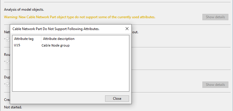
Note: If you are running the tool for the first time after a version upgrade and the analysis warns that the new network does not support attributes that exist in the old network, click Show details to see a list of those attributes. If the attributes are still needed, press Ctrl+E to export the list to a Microsoft Excel file, cancel the tool, ask your project administrator to add the attributes to the 'Cable Network Part' COS object, restart Plant Modeller, and then run the tool—the warning should no longer be displayed, and starting the operation converts the network and transfers the attributes to the new network.
-
-
Select the appropriate options for running the tool.
Show/hide details
-
Cable network parts check out – The option Check out all cable network parts is selected by default.
If some parts cannot be checked out and this will affect some of the cable routes, click Show details to see what those objects are. You may want to try to get their ownership before continuing with this operation; otherwise, the affected cable routes might be broken after the operation.
If you clear this option, the operation cannot be started.
-
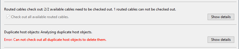
Routed cables check out – Select the option Check out all available routed cables if you want the tool to be able to modify all available routes so that they match the new network. Otherwise, it will only be able to modify the routes that are already checked out. As a result of this modification, the category of the cable routes can change from 'Routed' to 'Route Broken' or 'Route Changed'.
-
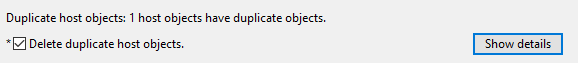
Duplicate host objects – If the model contains duplicate host objects, the option Delete duplicate host objects is shown and selected by default because duplicate objects would slow down the search for possible routes.
If you want to see what those duplicate objects are, click Show details.
If you clear this option, the operation cannot be started.
-
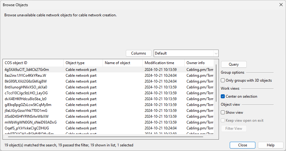
Missing cable tray connections – This section shows whether cable trays are positioned close to each other but are not connected according to the Connection tolerance setting. Select Show details to open the Browse Objects dialog, which lists the cable trays. If possible, recreating the cable routing network will connect these cable trays. Saving the changes in the cable trays to COS will save the connection statuses.
-
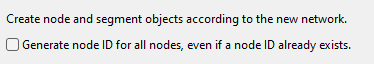
Create node and segment objects according to the new network
-
Generate node ID for all main nodes, even if a node ID already exists – Select this option to allow a node ID to be generated for all the main nodes in the new network. If this is not selected, a node ID is only generated for those main nodes that should have a node ID but do not yet have one.
Note: A node is a main node if it is the first or last node of a run, the first node of a penetration, a branch node, a major corner node, or any type of node that already has a node ID. A node is a corner node if the cable route changes its direction by 10 degrees or more. A corner node is a main corner node if the direction changes by more than 88 degrees.
-
Convert segments that contain cables to user-defined if they are not a part of the new network – Select this option to allow air jumps containing cables to be converted to user-defined segments when the segment would otherwise be deleted as not being part of the new network. When recreation is completed, these segments can be browsed by clicking Show details. Later, they can be listed with a query that includes the 'Cable Network Part' object type, selects the whole network, and uses a selection test that includes objects where 'Cable network part flags' is 'One of' 18 or 19.
-
-
Modify cable routes – Select how to handle minor changes in the length of cable routes.
-
Accept minor route changes automatically – Select this to allow the tool to handle small changes automatically.
-
Users need to accept all route changes – Select this to require the user to approve every change.
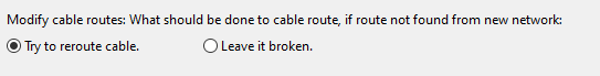
If the tool is preparing to perform a conversion from an older cable routing network, instead of selecting the options mentioned above, you will choose what the tool should do if the route of an existing cable cannot be found in the new network.
-
Try to reroute cable – Select this to try to find a new route for the cable. The rerouting is either automatic or manual, depending on how the old route had been defined. If the cable had been manually routed and reroute is not able to find a route using the manually defined node locations, it tries to find an automatic route for the cable.
This is the preferred option, but in a large model the operation might take some time.
-
Leave it broken – Select this to skip the broken routes and set their status to 'Route Broken'.
You can select this option if you know the changes in the model to be so big that most of the existing cable routes are no longer valid, or if you just want to tentatively check how many routes would get broken in the operation.
Note: Regardless of this option, if there are cables that cannot be checked out, the cable routes are left as they are but their category can still change, for example, from 'Routed' to 'Route Broken'.
-
-
Garbage collection – This step deletes cable routing network parts that are not used in the new network. If a network part is checked out by another work area and cannot be checked out here, the network part is marked as a garbage object, and it will be deleted when the current owner checks it in. The program does not use these garbage objects in cable routing.
-
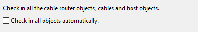
Check in the cable routing network and those cables and host objects that were checked out here – Select the option Check in all objects automatically if you want all the objects to be checked in when the creation of the cable routing network is completed. Other users will not be able to use the new network until the network has been checked in once.
Important: If you select this option, you will not be able to undo the operation and the changes made by the tool are permanent.
If you do not select this option, you will be able to click Cancel to restore the old network and cancel the check-outs (or even accept the new network but then undo it in Plant Modeller).
-
-
Click Start.
The tool checks out the existing cable network parts and routed cables, generates new cable network parts, adds existing user-defined nodes and segments to the new network, and tries to apply the existing cable routes to the new network.
-
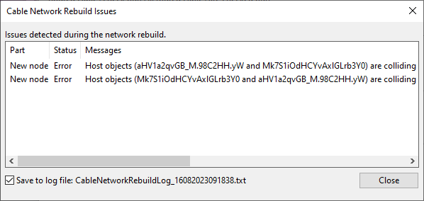
If any problems occurred, the Cable Network Rebuild Issues dialog opens. You can click a message row to view the problem in the 3D model; press Esc to return to the dialog. When you have reviewed all listed issues, close the dialog.
-
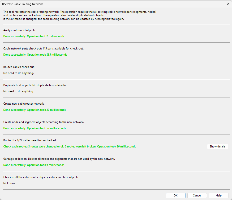
The Recreate Cable Routing Network dialog now shows the result of each step that was taken when regenerating the network.
-
Review the results, especially the errors (red text).
-
If the Routes for #/# cables need to be checked section indicates that one or more routes need to be checked, click Show details to see which routes they are and what their new status is.
Show/hide details
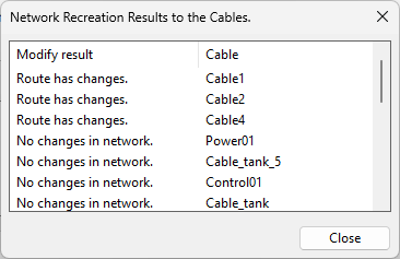
In the Network Recreation Results to the Cables dialog, cable routes can have the following statuses:
-
'No changes in network.' – The network where this cable is routed was not changed.
-
'No changes in route.' – The network was changed but the route of this cable remains unchanged.
-
'Route has changes.' – The network was changed and there are some changes in the route.
-
All the new nodes are in the same locations as the old nodes and only the node references had to be updated in the cable data (that is, the cables were not rerouted).
In the Category tree in Cable Manager, the category of these routes is not changed.
-
The first node, the last node, and all manually selected route nodes are still in the same locations, and the new network provides a valid route using these nodes.
In the Category tree in Cable Manager, these cables are moved to the 'Route Changed' category with the route status 'Changes'.
-
-
'Rerouted.' – The previous route of this cable could not be used and the cable was rerouted.
-
If manual reroute found a route, it means that the old route contained manually selected nodes that were kept and used in the new route.
-
If automatic reroute found a route, it means that the cable had a route in the old network and the program searched for a new route in the new network and was able to find one.
In the Category tree in Cable Manager, the rerouted routes are in the 'Route Changed' category with the route status 'Rerouted'.
-
-
'Left broken.' – The previous route of this cable could not be used and the route is now broken. Either the program could not or did not even try to reroute, depending on what you chose in the tool.
In the Category tree in Cable Manager, the broken routes are in the 'Route Broken' category.
-
'No rights to modify.' – The program did not have permission to edit this cable.
-
-
-
Close the Recreate Cable Routing Network dialog by doing one of the following:
-
Click OK to accept the changes and close the dialog.
(The button is not available if the program could not create the network.)
-
Click Cancel to undo the changes and cancel the check-outs made by the tool.
(The button is not available if you chose the option to check in all objects after the operation.)
-


Modify
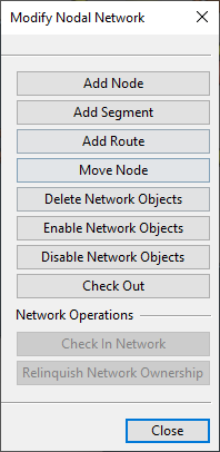
In the Nodal Network section, the Modify button opens the Modify Nodal Network dialog that allows you to modify the cable routing network by adding, enabling, disabling or removing user-defined nodes and segments.
-
Add Node – Adds a user-defined node to a location you pick from the model. If the insertion point is close to a generated segment, you are prompted whether to insert the node into the segment; you can also use the separate Insert into Line (L) command to ensure that a node is inserted into a segment.
You can undo previous insertions, one at a time, using Undo (U).
Press Enter or Esc to stop adding nodes.
-
Add Segment – Adds a user-defined segment between two nodes you pick from the model.
-
Add Route – Allows creating a route of user-defined nodes and segments by first picking an existing node as the first node and then inserting new nodes along the intended route; press Esc to stop the routing.
-
Move Node – Allows moving a user-defined node.
-
Delete Network Objects – Deletes a set of user-defined nodes and segments.
-
Enable Network Objects – Enables a set of previously disabled nodes and segments.
-
Disable Network Objects – Disables a set of nodes and segments to prevent the cable router from using them.
Note: This does not remove a cable that is already using the segment that you are disabling.
-
Check Out – Checks out the selected network parts. If the nodes are currently owned by a different site, the command automatically requests their ownership from that site.
-
Check In Network – Checks in all the network parts and saves the area model. Any changes in the network must be checked in before you can continue to use the cable router.
-
Relinquish Network Ownership – Transfers the ownership of all network parts from the local replica server upwards.
Network Operations
Node IDs
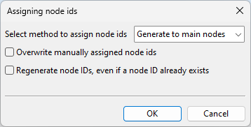
In the Nodal Network section, the Node IDs button opens a dialog for specifying how to set IDs to cable nodes.
-
Select method to set node IDs
-
Generate to main nodes – Select this to generate a new node ID for all main nodes. Nodes that already have manually or automatically set node IDs are not given new ones unless the relevant options below are selected.
Note: A node is a main node if it is the first or last node of a run, the first node of a penetration, a branch node, a major corner node, or any type of node that already has a node ID. A node is a corner node if the cable route changes its direction by 10 degrees or more. A corner node is a main corner node if the direction changes by more than 88 degrees.
-
Generate to selected – Select this to generate a new node ID for the selected nodes, according to the node ID settings. Nodes that already have manually or automatically set node IDs are not given new ones unless the relevant options below are selected.
-
Set manually – Select this to pick a specific node from the model and then manually enter a node ID for it.
Note: This manual assignment designates the node as a main node.
-
Remove from selected – Select this to remove the existing node ID from specific nodes that you pick from the model.
-
-
Overwrite manually set node IDs – Selecting this option allows the 'Generate to main nodes' and 'Generate to selected' methods to replace manually set node IDs with generated ones.
-
Regenerate node IDs, even if a node ID already exists – Selecting this option allows the 'Generate to main nodes' and 'Generate to selected' methods to replace generated node IDs with new ones.
For example, if generating node IDs to main nodes and both Overwrite… and Regenerate… are selected, all main nodes will receive a new ID, regardless of whether they already have one. If neither option is selected, only the main nodes that currently do not have an ID will receive one. If only one option is selected, the corresponding type of nodes will receive a new ID along with those main nodes that currently do not have an ID. Nodes that are not main nodes will not receive an ID, regardless of the selected options.
Check In
In the Nodal Network section, the Check In button checks in the entire cable routing network and saves the area model.
You can use this if the cable network parts were not checked in when you recreated the network.
Relinquish
In the Nodal Network section, the Relinquish button relinquishes the ownership of the network parts from the local replica server upwards.
You can use this if using online connection and the cable router network is being used or recreated at two sites. Ownerships are requested automatically.