Cable interference classes
Interference class is one of the properties that must be specified when creating a new 3D cable in the cable router. This property enables the cable router to distribute cables into stacks based on how they emit or tolerate interference.
In the Cable Router Setup dialog, the project administrator can add the required interference classes to the project configuration. For each interference class, the administrator can specify the shape of the cable stack (either a triangle or rectangle), determine whether stack size is constrained by factors other than available space, and define a minimum distance between adjacent stacks that have the same interference class.
Cable trays (and other cable ways) can be configured to allow multiple interference classes. This enables the cable router to put cables from different interference classes into the same segment. To avoid interference in these segments, in the cable router's settings the project administrator can define segregation distance between adjacent stacks that have different interference classes.
Defining interference classes
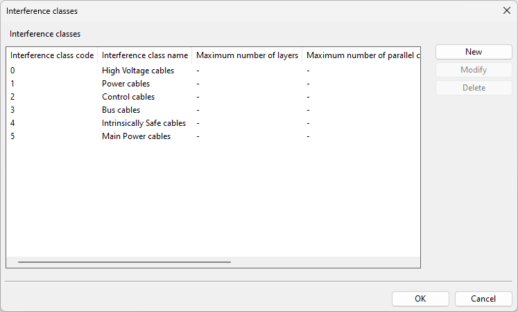
The project administrator can create, modify, and delete cable interference classes. There are some predefined interference classes that can be modified but not deleted.
Do the following:
-
In Plant Modeller, select Cabling tab > Cables group > Manager tool.
-
In the Cable Manager dialog, select Tools tab > Settings.
-
In the Cable Router Setup dialog, in Cable Router Settings > Cables, click the Define button of the Interference classes setting. The Interference classes dialog opens.
-
Define the required interference classes:
-
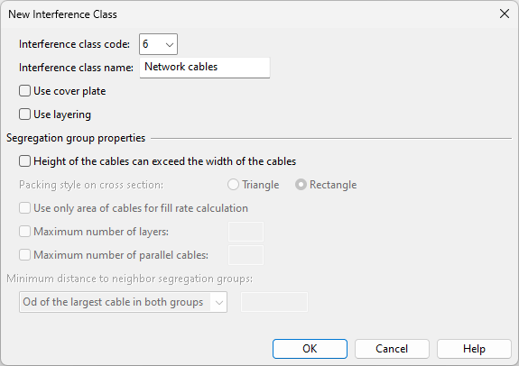
To create a new interference class, click New and define the Interference class settings.
-
To edit an existing interference class, select it from the list and click Modify.
-
To delete a user-defined interference class, select it from the list and click Delete.
-
-
Click OK to accept the changes.
Next, specify segregation between interference classes, as described in Defining segregation distances.
Interference class settings
Interference classes can have the following properties.
-
Interference class code – Specify the ordinal number (6–30) of the interference class.
-
Interference class name – Enter a descriptive name for the interference class.
-
Use cover plate – Select this option to specify that the cable stack should be covered with a plate. This sets the packing style to "Rectangle", and fill rate views show the cover plate as a line.
 Show/hide example
This example shows a cable tray with cables from three different interference classes, and one of them has the cover plate option enabled.
-
Use layering – Select this option to specify that the cables should be stacked in uniform layers, each layer's height determined by the thickest cable within that layer, using either triangular or rectangular packing style.
Show/hide example
This example shows a cable tray with cables from three different interference classes, and one of them has the layering option enabled. The segregation group contains cables of different sizes, the cables are in three layers, and each cable is aligned to the bottom of its layer. Having both thick and thin cables in the same layer leaves unusable empty space inside the layers.
Segregation group properties
A stack of cables, all belonging to the same interference class, is referred to as a segregation group. When one stack reaches its capacity, another one is formed until all cables have been placed or the segment is full. Segregation groups can either be spaced apart or placed right next to each other.
-
Height of the cables can exceed the width of the cables – Select this option to allow the height of a cable stack to be greater than its width. This can be useful when the program seems to be leaving too much space above the cables, and the other settings do not explain the gap. This option and layering cannot be used at the same time. If the cables do not fit into the cable tray and this option is enabled, the stack will overflow from above; if this option is disabled, the stack will overflow from the right side.
Show/hide example
This example shows a cable tray with cables from three different interference classes, and one of them has this option enabled.
Note: For best results, we recommend this option to be either enabled or disabled for all interferences classes that can exist in the same cable tray.
-
Packing style on cross section – Select whether the cross section of a stack of cables should form a Triangle or Rectangle. Using a cover plate enforces the rectangular packing style.
-
Use only area of cables for fill rate calculation – Select this option to calculate the fill rate solely based on the cable cross-sections. Typically, this results in a lower fill rate percentage, representing the physical space that the cables actually occupy. However, it does not directly indicate what part of the non-filled space the layering method may still utilize.
If this option is not selected (which is the default), the fill rate percentage includes both the layer cross-sections and the empty space that the layers cannot use. Generally, this leads to a higher fill rate percentage, more accurately reflecting the remaining space for parallel cables or additional layers.
-
Maximum number of layers – Select this option to set a maximum limit for the number of layers within a segregation group. Restricting the number of layers can leave more unusable space within the segment.
Note: The unusable space above a full segregation group is included in the fill rate percentage. However, if the Use only area of cables for fill rate calculation option is selected, then the space above the layers is not included in the fill rate, despite the fact that no additional cables can be added there.
Show/hide example
This example shows a cable tray that contains cables from a single interference class. The interference class uses triangular packing, and the maximum number of layers is 4, resulting in a single stack of cables (one segregation group).
-
Maximum number of parallel cables – Select this option to set a maximum limit for the number of parallel cables within a layer. A stack's height cannot exceed its width, so restricting the width will also restrict the height, and therefore result in more unusable space within the segment.
Note: The unusable space above a full segregation group is included in the fill rate percentage. However, if the Use only area of cables for fill rate calculation option is selected, then the space above the layers is not included in the fill rate, despite the fact that no additional cables can be added there.
Show/hide example
This example shows a cable tray that contains cables from a single interference class. The interference class uses triangular packing, and the maximum number of parallel cables is 3, resulting in two stacks of cables (two segregation groups).
-
Minimum distance to neighbor segregation groups – Specify how much spacing to add between consecutive stacks of cables from this interference class. The segregation areas increase the fill rate of the segment.
-
Od of the largest cable in both groups – Select this option to get the segregation distance from the outer diameter of the largest cable in the stacks.
-
Fixed distance – Select this option to specify the segregation distance as a fixed value (millimeters). If this is 0, there is no segregation area between the stacks.
If the cable ways allow multiple interference classes, note the following:
-
The program can utilize the segregation distances of different interference classes also here, if it improves the overall packing in the segment. That is, instead of spacing the stacks as designated here, it may move the stacks around and insert a different interference class between them.
-
The program can place a stack whose interference class has no minimum distance right next to a stack that does have one. To prevent this, make sure that all interference classes that might appear in the same segment have matching minimum distances.
-
Defining segregation distances
The project administrator can create, modify, and delete segregation definitions. These definitions specify the required distance between cables that belong to different interference classes. In fill rate views, the segregation distance between stacks from different interference classes looks exactly the same as the minimum distance between stacks from the same interference class. Both spacing methods create segregation areas that increase the fill rate of the segment.
This example shows a cable tray with cables from three different interference classes, and each interference class is segregated from the next one with a given amount of space.
Do the following:
-
In Plant Modeller, select Cabling tab > Cables group > Manager tool.
-
In the Cable Manager dialog, select Tools tab > Settings.
-
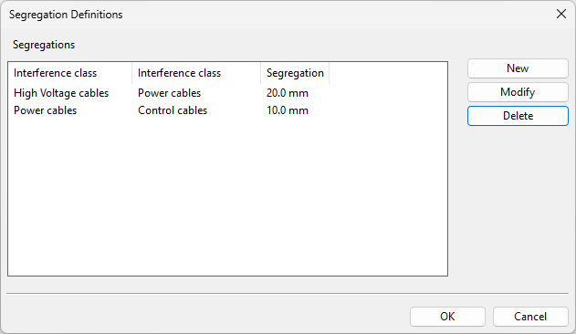
In the Cable Router Setup dialog, in Cable Router Settings > Network, click the Define button of the Define segregation distances setting. The Segregation Definitions dialog opens.
-
Define the required segregation distances:
-
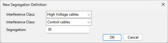
To create a new definition, click New, and specify the following settings.
-
Interference Class – Select the two interference classes whose distance from each other you wish to define.
-
Segregation – Specify how many millimeters of empty space to leave between the two interference classes.
-
-
To edit an existing definition, select it from the list, and click Modify.
-
To delete a definition, select it from the list, and click Delete.
-
-
Click OK to accept the changes.
Examples
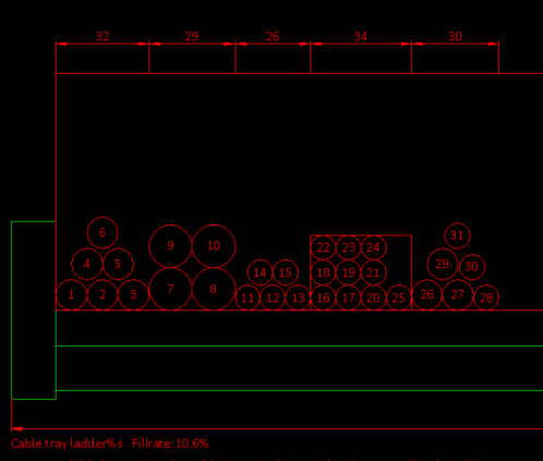
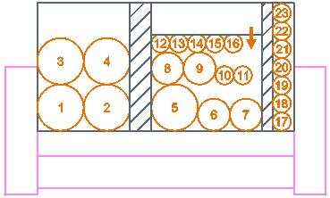
The following picture shows the fill rate view of a segment where all the cables belong to the same interference class which is set to use triangular packing, allows a maximum of three layers and three parallel cables, and specifies a fixed 5.0 mm distance between the groups.
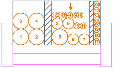
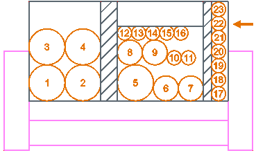
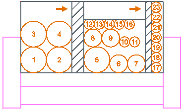
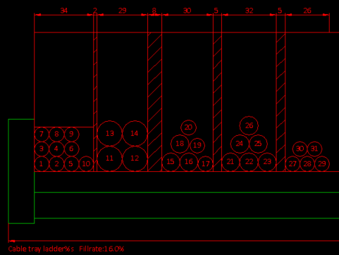
The following picture shows the fill rate view of a segment where the cables belong to different interference classes, the interference classes are using either triangular or rectangular packing style, one interference class requires a cover plate, and there are different segregation distances between the interference classes.
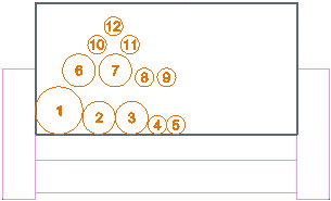
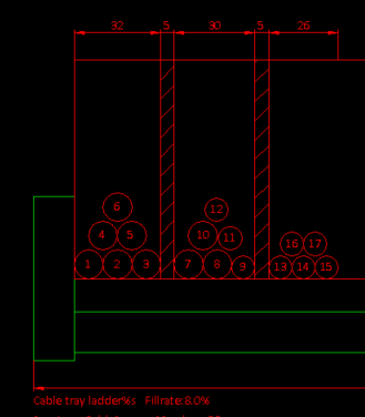
The following picture shows the fill rate view of a segment where at least some of the interference classes do not specify a minimum distance to adjacent groups, which allows the program to place the cables right next to ones that do require a minimum distance.