Cable fill rate views
The cable router calculates the space requirements of cables and allows the fill rate percentages of the cable ways to be shown in special fill rate views. A fill rate view shows a cross section of the cable way object and the fill rate percentage of each cable in the cable way. Fill rate views can be created and inserted to cabling documents in the document editor.
Fill rate calculation
The cable router calculates the fill rate percentage of the cable ways to indicate how densely the space is populated with cables.
The fill rate calculation considers the maximum space of the cable segment, the space occupied by currently assigned cables, and cable segregation and packing rules. The fill rate values are expressed in percent, and values close to 100% indicate that there is no more space for new cables in the cable way. For cable trays, the fill rate can be more than 100%, indicating that the physical capacity is currently being exceeded. However, the fill rate of an overfilled cable tray does not take into account available space that could possibly be utilized by using a different packing style.
The following picture illustrates an example scenario for calculating the fill rate of a cable way that contains two segregation groups and horizontal packing is being used:

Note that when using triangular packing, the program considers the sides of the allowed triangular area to be forbidden area, as indicated with light blue color in this example:

The program calculates the fill rate percentages as follows:
-
Calculate the bounding box of the cross section of an individual cable:
Cable cross-section area = CableOuterDiameter * CableOuterDiameter
-
Calculate the total cable space area, using the width and height values defined in the Dimension Table associated with the cable way part:
Cable space area = CableWidth * CableHeight
-
Calculate the fill rate:
Fill rate = ( Sum(Cable cross-section areas) + Sum (Forbidden areas) ) / Cable space area * 100
The fill rates are calculated whenever there is a need for a status check or there is a change that requires recalculation. For example:
-
When the user starts a new application session and opens the cable router, the program checks which existing cables use which segment.
-
When the user recreates the cable routing network and saves the changes to COS.
-
When a cable is changed.
For information on the settings that affect fill rate calculations, see Cable interference classes.
Cable segment fill rate views
A fill rate view, which can be created and added to a page in the document editor, shows a cross section of the cable way object and the cables in it, information about the cable way object, and a list of the cables. The annotation properties of the cross section drawing, and the information that is to be shown for the cable way and the included cables, are defined in the cable router settings.
Fill rate views for segments
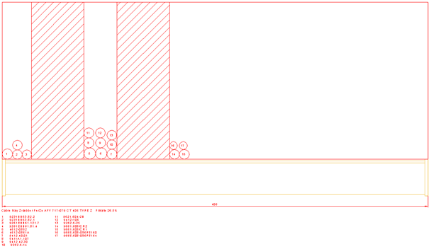
A fill rate view for a cable segment shows the cable way object as a cross section drawing, the cables as numbered circles, and the segregation areas between difference interference classes as hatches.
The cables are placed in the cable way object according to the calculations of the cable router.
You can also see the dimensions and information about the cable way object, and a numbered list of the cables included in the view. The cable list shows the information from the data request defined for the cables.
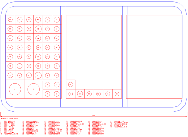
Fill rate views for penetrations
A penetration for cabling can be either a mass penetration or a Multi-Cable Transit (MCT) penetration where each cable uses a sealing module.
In the cross section view of an MCT-type penetration, the size of the sealing module is drawn as a rectangle around the cable.
Settings for creating fill rate views
Before starting to create fill rate views, the project administrator must specify the related cable router settings:
-
Specify how to arrange cables into groups based on interference classes. For more details, see Cable interference classes.

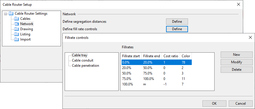
-
Specify the fill rate controls (cost ratio, coloring). For more details, see Network.
-
Select the annotation properties to use in cable drawings and define what kind of data to show for the cable trays, cable penetrations, and cables. For more details, see Drawing.

Creating fill rate views in the document editor
The process of creating a fill rate view and inserting it into a cable document is described in Create cable fill rate view into drawing.
Shifting cables up or down in fill rate views
In fill rate views, normally the cables are positioned so that the bottom of the cable section is at the level of the centerline of the cable way part. In some cases, this might mean that the cables are either too high or too low within the geometry of the cable way part. If this happens, the cable section can be moved upward or downward with the Dimension Table parameter "CableBottom", as described in Dimension table for cable tray part.