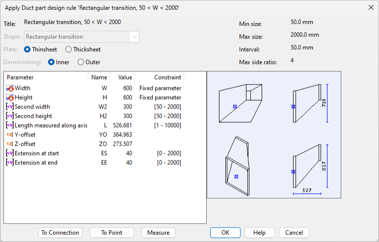
'Apply Duct part design rule' dialog
The Apply Duct part design rule dialog opens for a duct part that has adjustable parameters, such as when inserting a duct component to a straight duct piece, or when replacing a miter joint with a curve. This dialog displays parameters provided by the duct part design rule, and it shows how the current parameters affect the shape of the component.
If the user edits a parameter value that functions as a constraint to other parameter values, then those other values are automatically re-evaluated.
If the component that is being added is a transition piece, there are additional tools for selecting the connection or the point to which the transition should extend.

Editing the shape parameters of a duct component
In the Apply Duct part design rule dialog, you can define the shape of the duct part that you are adding to the model with the following tools and options.
-
(Plate – Currently this option is not used.)
-
Dimensioning – Select whether the dimensioning of the duct part should be Inner (plate thickness is excluded from width/height) or Outer (plate thickness is included in width/height).
-
Parameter – Those parameters that cannot be edited display a lock icon. Other parameter rows you can double-click to edit their value. See 'Edit value of shape parameter' dialog.
-
To Connection – This tool allows you to pick a connection point from an existing duct part. The program adjusts the shape parameters so that the transition you are inserting extends to (and takes its cross-section dimensions from) the specified connection point.
Note: If the duct piece from which the connection is picked has a flange or a frame, the transition piece is not extended to the connection face, and you must manually add a respective flange or frame to the end of the transition piece.
-
To Point – This tool allows you to select a point from the model. The program adjusts the shape parameters so that the transition you are inserting extends to the specified point.
-
Measure – This tool allows you to take a measurement by selecting two points from the model. After picking the two measurement points, press Esc twice to exit the tool. Then copy the measured value to the required parameter by double-clicking the parameter row and selecting Measured Value from the context menu of the "Edit value of shape parameter" dialog.