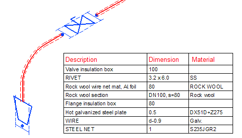
Insulation in isometric drawings
Isometric drawings can be set to show which pipes and components are insulated.
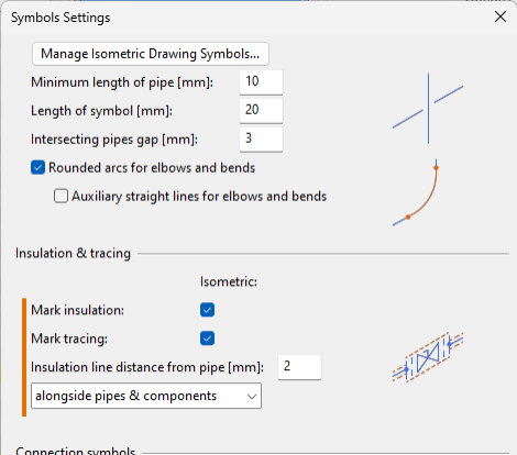
Symbol settings for insulation
The insulation markings can be configured in the Symbol Settings dialog. In the Insulation & tracing section, you can select the distance from the insulation symbol to a pipe or component, and you can select where insulation symbols are to be shown.
To access these settings, do the following:
-
Piping Isometrics & Spools: Select the application icon in the CADMATIC desktop and Object > Settings, and then Symbols from the context menu. See Symbols.
-
Plant Modeller: Select File > Options > Shared Settings > Documents > Isometric Drawing > Symbols. See Shared Settings.
Visualization settings for insulation
The visualization of the insulation markings can be configured in the Color, Lineweight & Layer Settings dialog. You can select the color, the lineweight, and the layer that insulation markings are to use.

To access these settings, do the following:
-
Piping Isometrics & Spools: Select the application icon in the CADMATIC desktop and Object > Settings, and then Colors, Pens, Layers & Font from the context menu. See Colors, Lineweight & Layer Settings.
-
Plant Modeller: Select File > Options > Shared Settings > Documents > Isometric Drawing > Colors, Lineweights & Layers. See Shared Settings.