Shared Settings
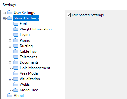
In the Settings dialog of Plant Modeller, the Shared Settings section allows the project administrator to define settings that affect all project users. Therefore, only administrators can make changes here, and only when the Edit Shared Settings option is enabled. Selecting this option or opening the Settings dialog with this option already enabled automatically checks out the related COS object from the project database, so that another administrator cannot edit it at the same time. Closing the dialog checks in the COS object again or cancels the checkout if no changes were made.
Editing these settings stores them first in the administrator's local configuration file …\<project>\<workspace>\<area>\main_mmt\appdefaults, and then the program updates them to the project database, to the COS configuration object Configuration > Plant Modeller > Shared settings. When a user launches Plant Modeller, or updates the area model, or opens the Settings dialog, the latest changes are updated to the user's local configuration file.
Font
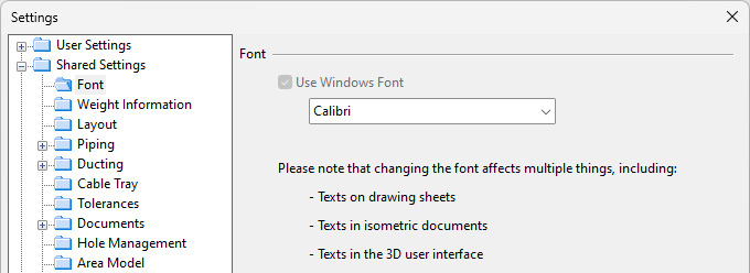
In the Font settings, you can select which Microsoft Windows font to use. If an old drawing uses a font that is no longer available, the Arial font is used instead.
Weight Information
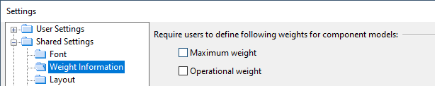
In the Weight Information settings, you can select which weight values must be defined for component models:
- Maximum weight
- Operational weight
Layout
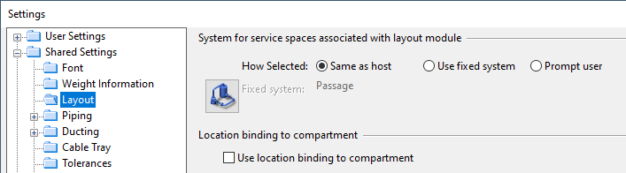
In the Layout settings, you can specify how to assign a system to a service space that is attached to a structural component or equipment.
- Same as host – Select this if service spaces should automatically be assigned to the system of their host object.
- Use fixed system – Select this if service spaces should automatically be assigned to a specific system. Click
 to select the system.
 - Prompt user – Select this if inserting a service space should always prompt the user to select the system.
Location binding to compartment
- Use location binding to compartment – Select this to allow the Layout tab to display tools for binding equipment to compartment and to allow the program to move equipment to the bound location if either the compartment or the equipment has been moved.
Location binding to compartment
Piping
Isometric Checks | Isometric Groups | Routing | Standard Component | Penetrations | Spool Checks | Spools
Isometric Checks
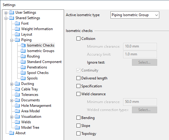
In the Isometric Checks settings, you can select which checks to run for pipes that are included in isometric drawings.
Active isometric type
Select the isometric group type whose settings you want to change. See Active group type.
Isometric checks
-
Collision – The program checks whether the pipes collide with other objects. If enabled, specify the following settings:
-
Minimum clearance – Specifies the tolerance value to use in clearance violation checks (2–10000 mm). A clearance violation is reported if objects are closer to each other than what is specified in this field.
-
Accuracy limit – Specifies the tolerance value to use in collision checks (1-100 mm). A collision is reported if objects collide at least by the amount specified in this field.
-
Ignore test – Click Select and define a query if you want collision tests to ignore some objects.
Tip: Collision checks can also be run from Tools > Collisions—see Collisions.
-
-
Continuity – This is always on. The program checks whether the piping is continuous and whether the ends are connected to other objects or at least close to a possible connection.
Tip: Continuity checks can also be run from Piping > Check / Change > Check continuity of pipelines in set—see Check continuity of pipelines in set.
-
Delivered length – The program compares the cut lengths of the pipes in the piping isometric to the 'Default length of delivered pipes' value specified in the pipe routing options or to the (overriding) value of the 'DPL' tag if defined in the Corporate Catalog–see Routing. For parts that are to be bent with a bending machine, the cut lengths also consider elongation during the bending process as well as potential cut-away lengths at the ends of pipes. This manufacturability check fails if the pipes exceed the specified delivery length.
-
Specification – The program checks whether the piping complies with the pipeline's piping specification.
-
Weld clearance – The program checks whether the weld points are too close to each other. If enabled, specify the minimum clearance to have between consecutive weld points and select which connection types require weld clearance checking.
-
Bending – The program checks whether parts that are to be bent with a bending machine might cause problems, for example, by being too short for the machine—see Bending Machines.
-
Slope – This includes the following checks:
-
Design slope violations: The program checks whether a Piping Part object has (calculated) geometric slope as well as the 'Design slope' (.K0) attribute that specifies the minimum slope ratio for that object.
If a pipe has both and geometric slope is less than the minimum slope, slope check fails and reports that "Parts violate set design slope".
-
Traps: The program checks whether a pipe run first goes downward and then turns upward, thus forming a trap which might prevent the emptying of the pipe by gravity alone.
If such places are found, slope check fails and reports that "Parts form trap".
-
-
Topology – The program runs a topology check on P&I diagrams that contain the pipelines of the isometric groups. The results can be viewed in the Topology Comparison Results dialog–see Compare topology.
For more information, see Isometric Check Results.
Isometric Groups
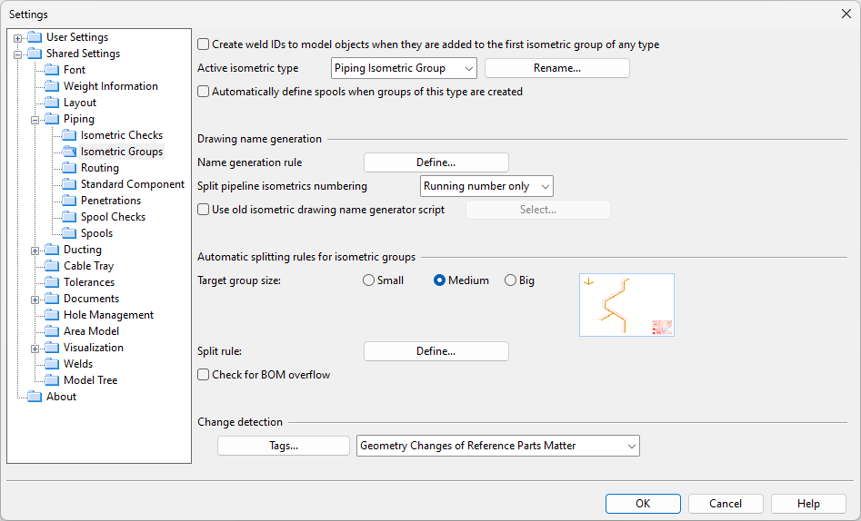
In the Isometric Groups settings, you can define how to generate names for isometric groups, determine where one isometric group ends and another one begins, and specify what kind of changes require isometric groups to be updated.
-
Create weld IDs to model objects when they are added to the first isometric group of any type – Select this option to enable the automatic assignment of weld IDs to the connection point attributes of piping parts that have welded connection faces. Connections to onto-line parts with 'WELD' in their keyword are assigned weld IDs regardless of the connection type. Weld IDs are added when a piping part is included in an isometric group for the first time, and they are removed when the part is removed from its last isometric group. The IDs use consecutive numbering throughout the pipeline, and the ID string can be customized using the PmScH_GetNodeWeldId script hook.
Note: If the similar setting for Spools is also enabled, the weld ID is first assigned when an object becomes a member of either group type, and consecutive numbering is applied across both group types. This ensures that both isometric drawings and pipe spool drawings display the same weld ID for the same object.
Tip: The program uses internal rules to determine which parts receive the 'Weld ID' attribute. If a drawing is missing weld ID labels, the attribute may have been assigned to a connected part not shown in the drawing. You can manually adjust the assignment by moving the 'Weld ID' attribute to the correct part, as described in Node attributes.
-
Active isometric type – Select the isometric group type whose settings you want to change. Click Rename if you want to rename the selected isometric group type in the current project. See also Active group type.
-
Automatically define spools when groups of this type are created – Select this option to specify that creating an isometric group should automatically create spools for the included geometries. This can only be enabled for one isometric group type at a time. The naming of the spools can be defined in the Spools options.
Note: The option is only available if Use pipe spool drawings is not selected in the Pipe Spool Drawing options.
These settings define how the program generates names for isometric drawings.
-
Name generation rule – The Define button opens Edit Name Generation Rules dialog where you can define rules for generating names for isometric groups. The name of the isometric group becomes the name of the isometric drawing.
-
Split pipeline isometrics numbering – If the piping is divided into isometric groups and the name generation rules add a numerical identifier to the name, here you can select whether the running number should be followed by the total number of related isometric groups:
-
Running number only
-
Running/total
-
Running(total)
-
Automatic splitting rules for isometric groups
These settings define how the piping is to be divided into multiple isometric groups when automatic splitting is enabled as described in Create New Isometric Group.
-
Target group size – Select how densely the drawings should be populated. A small group size results in sparsely populated drawings that are easier to read, but the small number of objects per drawing increases the total number of separate drawings.
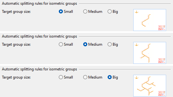
Note: After the initial automatic splitting, the user can adjust the drawing density of each pipeline separately. See Auto split (I).
-
Split rule – Click Define to open the Edit Iso Splitting Rule dialog where you can define rules that designate where one isometric group ends and another begins.
-
Check for BOM overflow – Select this option to allow automatic splitting to check that the members of each isometric group fit into the BOM table of the drawing sheet.
These settings define how the program detects whether the contents of isometric groups have changed so much that the groups should be updated.
-
Click Tags to select the attribute tags to use in change detection.
Note: If you add or remove change detection tags when isometric documents already exist, isometric groups that have a document do not use the new set of tags until the document is recreated or updated.
-
Select from the drop-down list whether changes in piping geometry should be a reason to update the isometric groups.
Routing
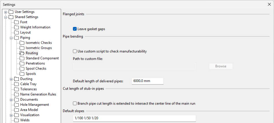
In the Routing settings, you can configure the following options.
Flanged joints
- Leave gasket gaps – If selected (default), pipe routing leaves gaps whose size equals the size of the compressed thickness of the gasket.
Pipe bending
-
Use custom script to check manufacturability – Select this if you have a custom script for checking pipe manufacturability, and then specify the file location.
-
Default length of delivered pipes – Specify the default length of pipes that are delivered to bending.
You can override this default value with a value that is specific to a Dimension Table, Catalog Part or Part Size: create a COS attribute with the tag 'DPL' (the Example Project has one), assign the attribute to the required Dimension Table, Catalog Part or Part Size, and define the length value to be used. If there is no 'DPL' tag, then the default value from shared settings is used.
Cut length of stub-in pipes
-
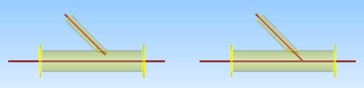
Branch pipe cut length is extended to intersect the center line of the main run – If selected, branch pipe's cut length should always be calculated to the center line of the main pipeline. In the example below, the branch pipe on the left is calculated to the edge of the main pipeline (option disabled; default), and the branch pipe on the right is calculated to the center of the main pipeline (option enabled).
Note: This setting is also applied when calculating the pipe length of stub-in branches in drawings created in Piping Isometrics & Spools.
Default slopes
-
Specify the default slope values as a space-separated list. Using these values, the piping designer can set sloping to a new pipe from Piping > Routing or from Pipe routing context menu.
Standard Component
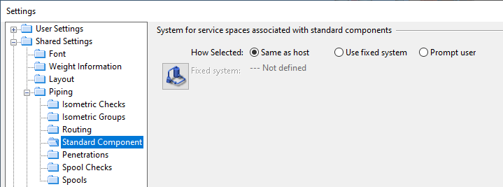
In the Standard Component settings, you can specify how to assign a system to a service space that is attached to a standard component.
- Same as host – Select this if service spaces should automatically be assigned to the system of their host object.
- Use fixed system – Select this if service spaces should automatically be assigned to a specific system. Click to select the system.
- Prompt user – Select this if inserting a service space should always prompt the user to select the system.
Penetrations
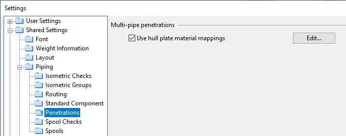
In the Penetrations settings, you can configure the following option.
Multi-pipe penetrations
-
Use hull plate material mappings – If selected, by default the multi-pipe penetration tool described in Multi-pipe penetration selects materials based on hull plate material mappings and target plate thickness; click Edit to define the mappings as described in Hull plate material mappings. Designers can override the automatic selection by selecting another material from the library.
If not selected, by default the multi-pipe penetration tool selects the last used material, and designers can select another material from the library, if needed.
Note: In the CADMATIC example project, the bulkhead plate of 'room_0' and the hull plates of training rooms have predefined attribute mappings for hull plate materials.
Spool Checks
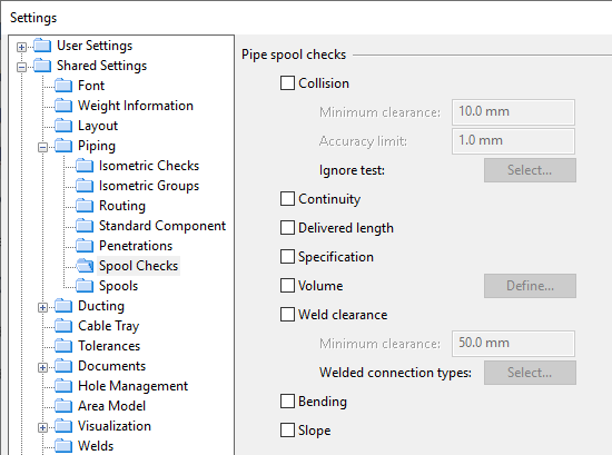
In the Spool Checks settings, you can select which checks to run for pipe spools.
Pipe spool checks
-
Collision – The program checks whether the pipe spool collides with other objects. If enabled, specify the following settings:
-
Minimum clearance – Specifies the tolerance value to use in clearance violation checks (2–10000 mm). A clearance violation is reported if objects are closer to each other than what is specified in this field.
-
Accuracy limit – Specifies the tolerance value to use in collision checks (1-100 mm). A collision is reported if objects collide at least by the amount specified in this field.
-
Ignore test – Click Select and define a query if you want collision tests to ignore some objects.
Tip: Collision checks can also be run from Tools > Collisions—see Collisions.
-
-
Continuity – The program checks whether the piping is continuous and whether the ends are connected to other objects or at least close to a possible connection.
Tip: Continuity checks can also be run from Piping > Check / Change > Check Continuity of Pipelines in Set—see Check continuity of pipelines in set.
-
Delivered length – The program compares the cut lengths of the pipes in the pipe spool to the 'Default length of delivered pipes' value specified in the pipe routing options or to the (overriding) value of the 'DPL' tag if defined in the Corporate Catalog–see Routing. For parts that are to be bent with a bending machine, the cut lengths also consider elongation during the bending process as well as potential cut-away lengths at the ends of pipes. This manufacturability check fails if the pipes exceed the specified delivery length.
-
Specification – The program checks whether the piping complies with the pipeline's piping specification.
-
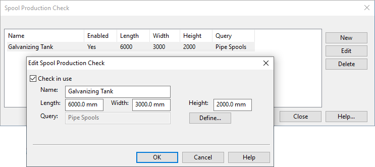
Volume – The program checks whether the pipe spool fits inside a container used in the prefabrication phase, such as a galvanizing tank or a shipping box. Clicking Define opens the Spool Production Check dialog where you can define the dimensions of these boxes and disable the ones that should not be checked. For more information, see Spool production check.
-
Weld clearance – The program checks whether the weld points are too close to each other. If enabled, specify the minimum clearance to have between consecutive weld points and select which connection types require weld clearance checking.
-
Bending – The program checks whether parts that are to be bent with a bending machine might cause problems, for example, by being too short for the machine—see Bending Machines.
-
Slope – This includes the following checks:
-
Design slope violations: The program checks whether a Piping Part object has calculated geometric slope as well as the 'Design slope' (.K0) attribute that specifies the minimum slope ratio for that object.
If the object has both of them and the geometric slope is less than the design slope, the slope check fails and reports that "Parts violate set design slope".
-
Traps: The program checks whether a pipe run first goes downward and then turns upward, thus forming a trap which might prevent the emptying of the pipe by gravity alone.
If such places are found, the slope check fails and reports that "Parts form trap".
Note: This check is only done for parts that belong to the same spool. If a spool that goes downward is connected to another spool that goes upward, the slope check does not report a trap.
-
Spools
In the Spools settings, you can set options that affect creating and updating of pipe spools and spool documents.
Pipe spool
-
Create weld IDs to model objects when they are added to a Pipe Main Document group – Select this option to enable the automatic assignment of weld IDs to the connection point attributes of piping parts that have welded connection faces. Connections to onto-line parts with 'WELD' in their keyword are assigned weld IDs regardless of the connection type. Weld IDs are added when a piping part is included in a pipe main document group for the first time, and they are removed when the part is removed from its last pipe main document group. The IDs use consecutive numbering throughout the pipeline, and the ID string can be customized using the PmScH_GetNodeWeldId script hook.
Note: If the similar setting for Isometric Groups is also enabled, the weld ID is first assigned when an object becomes a member of either group type, and consecutive numbering is applied across both group types. This ensures that both isometric drawings and pipe spool drawings display the same weld ID for the same object.
Tip: The program uses internal rules to determine which parts receive the 'Weld ID' attribute. If a drawing is missing weld ID labels, the attribute may have been assigned to a connected part not shown in the drawing. You can manually adjust the assignment by moving the 'Weld ID' attribute to the correct part, as described in Node attributes.
-
Spool generation rule – Click Define to define rules for generating of pipe spools. You can affect spool numbering and how spools are automatically split into separate spools at a system or pipeline boundary, or where a specific part type is used, for example.
-
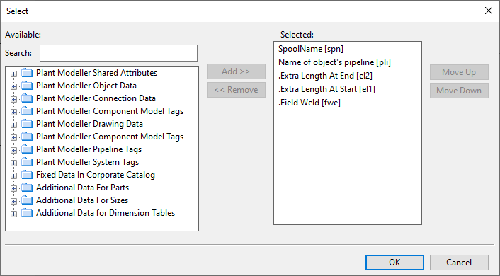
Change detection – Click Select to define which attributes should be tracked for changes. For example, by tracking the attributes field weld and extra length, adding field weld or extra length to a spool that already has a spool drawing allows the document status to be automatically set to 'Changed'.
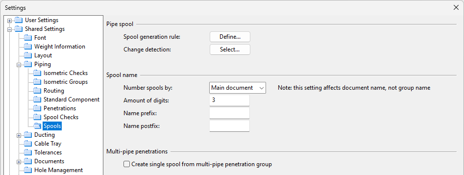
Spool name
-
Number spools by – Select how to name spool documents. (The naming of isometric documents is always based on the pipeline.)
-
Main document – Spool documents are named using the format MainDocument-Spool.
-
Line – Spool documents are named using the format MainDocument-Pipeline-Spool.
Note: The option is only available if Use pipe spool drawings is selected in the Pipe Spool Drawing options.
-
-
Amount of digits – Specify the number of digits to use (2–4) when numbering spools. This does not include the prefix and postfix characters. Examples:
- 2 digits: 01
- 4 digits: 0001
- 4 digits with character # as both prefix and postfix: #0001#
-
Name prefix – You can specify a prefix that adds up to two characters in front of the spool name. Prefixes cannot contain numbers.
-
Name postfix – You can specify a postfix that adds up to two characters in front of the spool name. Postfixes cannot contain numbers.
Multi-pipe penetrations
-
Create single spool from multi-pipe penetration group – If selected, a multi-pipe penetration group can be assigned to a main group and the pipes are handled as a single spool in Piping Isometrics & Spools. (This option has no effect if you manage pipe spools on the Pipe spools tab of Plant Modeller.)
Ducting
Routing | Service Space | Duct Spool
Routing
In the Routing settings, you can configure the following options.
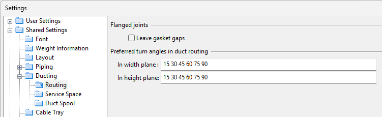
Flanged joints
-
Leave gasket gaps – Select this option to show the gasket gap in flanged duct connections.
Preferred turn angles in duct routing
These settings enable you to define preferred turn angle values that users can then refer to when routing an air duct and the duct line changes its direction—see Show preferred turn angles for details.
Define the preferred turn angles as space-separated lists where each angle value is between 1 and 90—one list for the width plane, and another for the height plane.
-
In width plane – Specify the preferred turn angles for ducts parallel to the width plane.
-
In height plane – Specify the preferred turn angles for ducts parallel to the height plane.
Service Space
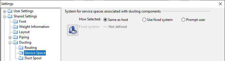
In the Service Space settings, you can specify how to assign a system to a service space that is attached to a ducting component.
- Same as host – Select this if service spaces should automatically be assigned to the system of their host object.
- Use fixed system – Select this if service spaces should automatically be assigned to a specific system. Click to select the system.
- Prompt user – Select this if inserting a service space should always prompt the user to select the system.
Duct Spool
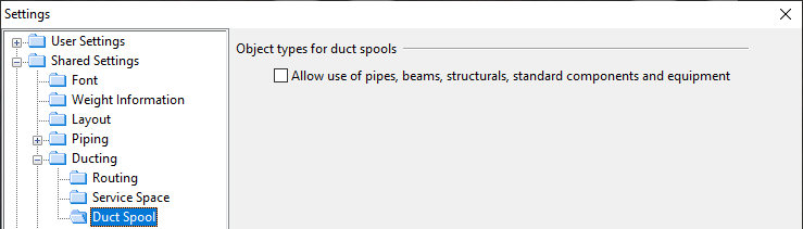
In the Duct Spool settings, you can allow objects that are not duct components to be included in duct spools.
Cable Tray
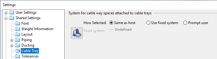
In the Cable Tray settings, you can specify how to assign a system to a service space that is attached to a cable tray.
- Same as host – Select this if service spaces should automatically be assigned to the system of their host object.
- Use fixed system – Select this if service spaces should automatically be assigned to a specific system. Click to select the system.
- Prompt user – Select this if inserting a service space should always prompt the user to select the system.
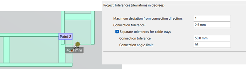
Tolerances
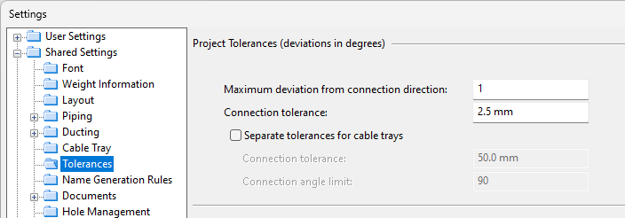
In the Tolerances settings, you can set tolerance values for routing in general and, separately, for cable trays.
-
Maximum deviation from connection direction – Specify the maximum angle between the direction of a routed object and the selected connection. This tolerance defines how many degrees the two directions can differ from being opposite to each other.
-
Connection tolerance – Specify the maximum distance used to connect two points, such as when joining two independently routed pipes.
-
Separate tolerances for cable trays – Select this option to set tolerances for recognizing cable trays as part of the same run. If the cable trays belong to different systems, these systems must have the same System Role setting.
Specify the maximum distance (0.5–50 mm) used to include cable trays in the same run.
Note: The minimum length for straight cable tray parts is the maximum connection tolerance distance + 1 mm ( = 51 mm). Preventing very short tray parts helps keep the network more uniform.
Specify the maximum angle (0–135°) for including cable trays in the same run. If this value is 0, the ends of the cable trays must be directly opposite to each other.
Tip: Higher tolerances allow for more approximate cable tray routing. The tolerance values are utilized, for instance, when using the Join command to merge two cable trays, or when using the Include in selection… Others in run (Alt+R) method to select a set of cable tray parts. Higher tolerances may also simplify the generation of the cable routing network. Cable trays that are not physically connected but fall within the tolerance values do not require an air jump, and a cable routing node is not needed if the routing direction is the same.
In this example, the tolerance settings allow two cable trays whose connection points are less than 50.0 mm apart and at an angle less than 93° to be considered part of the same run.
Name Generation Rules
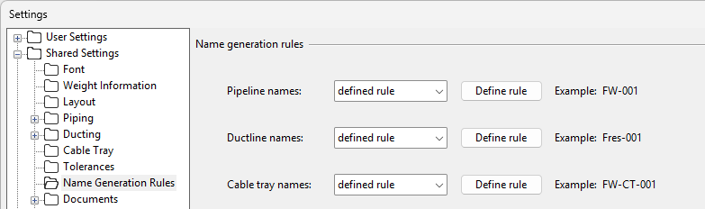
In the Name Generation Rules settings, you can specify whether new line names should be generated via a script or line type specific rules.
If you select the 'defined rule' option, clicking Define rule opens the Edit Name Generation Rules editor of the given line type.
Note: P&ID and Plant Modeller use the same line name generation rules. Changing the rules for pipelines, ductlines, or cable trays in one application will affect the generating of line names in both of them.
Documents
Drawing AutoSave | General Drawing | Isometric Drawing | Duct Spool Drawing | Pipe Spool Drawing | Weld Drawing | M-File Output | Revision Info
Drawing AutoSave
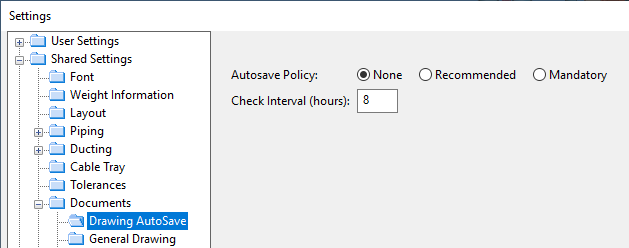
In the Drawing AutoSave settings, you can configure the following options.
-
Autosave Policy – Select the policy for prompting the user to save locally saved documents to COS before exiting Plant Modeller.
-
None – No prompting.
-
Recommended – The user is prompted to save, but saving is optional.
-
Mandatory – The user is prompted to save and saving is mandatory.
-
-
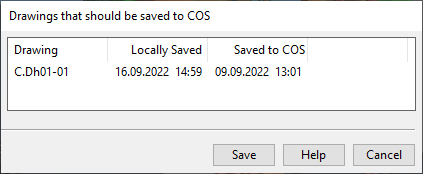
Check Interval (hours) – Specify how often to prompt the user.
If saving is recommended or mandatory and the interval is reached, trying to close Plant Modeller opens a list of drawings that should be saved to COS. If saving is mandatory, the dialog cannot be closed without saving.
General Drawing
In the General Drawing settings, you can configure the following options.
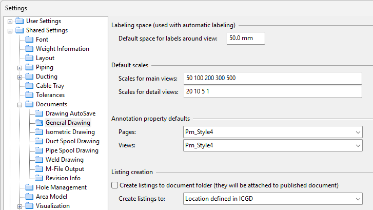
Labeling space
-
Default space for labels around view – Define the default margin for automatic labeling in drawings. When working in a drawing, designers can override this default setting by dragging the margin lines to more appropriate locations.
Default scales
-
Scales for main views, Scales for detail views – Define the scaling values that a designer can select from, for example, when adding a drawing view to the active page (Add to Current Page) or changing the scale of a view that is already on the active page (Set scale).
Annotation property defaults
-
Pages, Views – Select the default annotation properties for annotating the pages and the drawing views of all document types. When working in a drawing, designers can override these default settings as described in Property Defaults.
Listing creation
These settings define where to save listings that are defined in the ICGD of the document. Listings are saved when a document is regenerated in the document object browser or when listings are generated with Output print and lists or with Generate all listings in the document editor.
-
Create listings to document folder – Select this option to embed listings in the document that is saved in COS. You can select an additional or alternative location in Create listings to.
-
Create listings to – You can select listings to be saved in a specific location, in addition to or instead of the document folder.
-
Location defined in ICGD – Listings are saved in the location defined in the ICGD.
-
Location defined here – Listings are saved in a fixed location. Select the location by clicking Browse.
-
Prompt user always for location – Generating a listing prompts the user to select where the listing should be saved.
-
Only to document folder – Listings are only saved in the document folder.
-
None – Listings are not saved, even if a saving location is defined in the ICGD.
-
Isometric Drawing
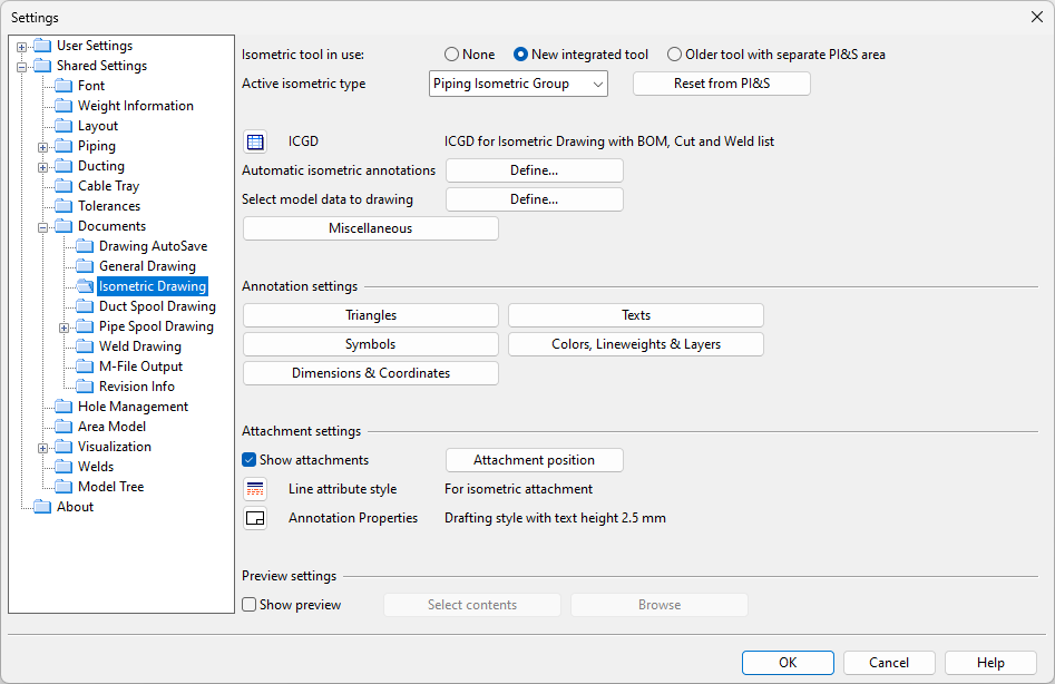
In the Isometric Drawing settings, you can specify how Plant Modeller generates isometric drawings.
-
Isometric tool in use
-
None – Select this option if you do not need to create or manage piping isometrics. When selected, Documents tab has no buttons for accessing piping isometric documents.
-
New integrated tool – Select this option to manage and store piping isometrics in the Plant Modeller area. When selected, the Plant Modeller ribbon has a Piping isometric tab for creating piping isometrics, the Documents tab has a Piping isometric documents button for opening isometric drawings in the Document editor of Plant Modeller, and from the document editor an isometric drawing can be opened for drafting in the Isometric view editor.
-
Older tool with separate PI&S area – Select this option to manage and store piping isometrics in the Piping Isometrics & Spools area. When selected, the Documents tab has a Piping isometrics button for creating isometrics and opening isometric drawings in the Piping Isometrics & Spools application.
-
-
Active isometric type – Select the isometric group type whose settings you want to change. See Active group type.
-
Reset from PI&S – This button retrieves the settings that have been used to create isometric drawings in the Piping Isometrics & Spools application, so that the same settings can be used to create isometric drawings in Plant Modeller. You are prompted to confirm the action.
-
ICGD – Click
 to select the ICGD to use for isometric drawings.
 -
Automatic isometric annotations – Click Define to define settings for automatic annotation of isometric drawings. For details, see Automatic Annotation Settings.
-
Select model data to drawing – Click Define to define settings that affect exporting of isometric drawings. For details, see Select Model Data to Drawing.
-
Miscellaneous – This button opens the dialog described in Miscellaneous Settings (options not relevant to new integrated tool are hidden).
-
Triangles – Opens the dialog described in Triangles.
-
Symbols – Opens the dialog described in Symbols.
-
Dimensions & Coordinates – Opens the dialog described in Dimensions & Coordinates.
-
Texts – Opens the dialog described in Texts.
-
Colors, Lineweights & Layers – Opens the dialog described in Colors, Lineweight & Layer Settings.
-
Show attachments – Select this option to include 3D attachments in isometric drawings. Click Attachment position to open a dialog where you can define how to position the attachments, as described in 3D Attachments.
-
Line attribute style – Click
 to select the default line attribute style to use in attachments.
 -
Annotation Properties – Click
 to select the default annotation properties to use in attachments.
You can open a preview window that shows how the settings affect the appearance of isometric documents. Requires that at least one isometric group has been created on the Piping isometric tab.
-
Show preview – Select this option to open a preview of an isometric document that uses the current settings.
-
Select contents – Opens a dialog where you can select which isometric group to show in the preview window.
-
Browse – Allows browsing the document in the preview window. Press Esc to return to the settings.
Duct Spool Drawing
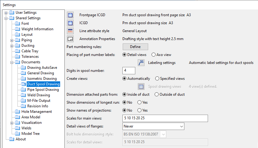
In the Duct Spool Drawing settings, you can specify how Plant Modeller generates duct spool drawings. Modifications to any of these settings will become effective only for duct spool drawings created or regenerated after the setting has been changed.
-
Frontpage ICGD – Click
to select the ICGD for the front page of duct spool drawings. -
ICGD – Click
to select the ICGD for duct spool drawings. -
Line attribute style – Click
to select the default line attribute style to use in duct spool drawings. -
Annotation Properties – Click
to select the default annotation properties to use in duct spool drawings. -
Part numbering rules – Click Define to select whether duct spool drawings should have automatically generated part numbers and to define the part numbering rules. See Part Numbering Rules.
-
Placing of part number labels – Select whether part number labels should be added to the detail views of individual parts or to axonometric views. If you select Axo view, click
 to select the labeling settings to use.
 -
Digits in spool number – Specify the number of digits to use (2–4) when numbering spools.
-
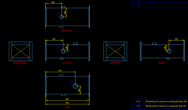
Create views – Select whether to create views automatically or using a specified view as described in Spool Drawing Views.
-
Dimension attached parts from – Select whether attached parts are dimensioned from Inside of duct or Outside of duct.
-
Show dimensions of longest run – Select whether the longest run of duct spools should be dimensioned.
-
Show names of projections – Select whether the names of standard projections should be displayed in duct spool drawings, as showed in the image below.
-
Scales for main views – Specify the scales for main views.
-
Detail views of flanges – Select when to create detail views of flanges:
- Never
- Always
- Only at component connections
-
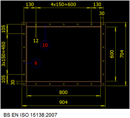
Bolt hole dimensioning style – Select the style for dimensioning of bolt holes: BS EN ISO 15138:2007 or Default. If flange is connected to a flanged component, then it may be that the bolt hole arrangement does not match BS EN ISO 15138:2007 and the Default style must be used.
This is a per-project setting, and you can have only one style active that applies to all duct spool drawings that are generated.
Note: If you change this value, then you probably need to change the X-offset in duct design rules for rectangular flanges, so that the first hole is measured correctly either from the inner corner of the duct (BS EN ISO 15138:2007) or from the outer edge of the flange (Default).
-
Scales for detail views – Specify the scales for detail views.

Part Numbering Rules

Part numbering rules for duct spool documents
- Generate part numbers – If selected, the other settings in this dialog are used for generating part numbers in duct spool documents. If not selected, existing part numbers will be removed from all duct spool documents when a designer opens any of them.
- Part numbering per spool – If selected, part numbering restarts for each spool within the same main document. If not selected, part numbers are shared across all spools in the main document.
- Part numbers are frozen in publications – If selected, the part numbers used in a previous document revision cannot be re-distributed to the parts of a new revision.
Select how uniqueness of part numbers is defined
-
Part numbering rule – Select which part numbering logic to use:
-
'Each part has its own part number'
-
'Same geometric shape, same part number'
-
'Same catalog part or component model, same part number'
-
'Custom rule' – Selecting this method enables the custom rule properties:
- Use geometric shape
- Use catalog part or component model
Note: We recommend selecting one of the three predefined rules, if possible. Using a custom rule requires the program to process much more data, which can make generating of part numbers slower than when using the other methods.
-
-
Select – Opens a dialog for adding more conditions to the rule. The predefined methods only allow adding Plant Modeller Shared Attributes, but custom rule allows adding any Plant Modeller object properties.
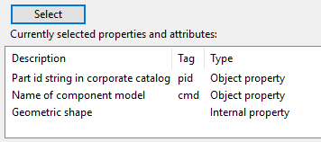
Currently selected properties and attributes
This section displays the object properties and attributes that currently define how the program determines which parts get unique part numbers. For example, if you have selected the predefined numbering rule 'Same geometric shape, same part number', the list shows that all parts that have the same pid value, cmd value, and geometric shape will get the same part number.
Pipe Spool Drawing
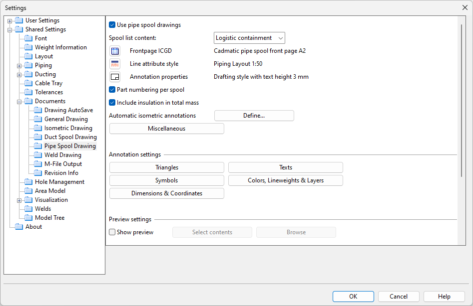
In the Pipe Spool Drawing settings, you can specify how Plant Modeller generates pipe spool drawings.
Use pipe spool drawings – If selected, the other settings in this view become enabled, and pipe spool related functions are available on the Pipe spools tab. See Pipe spools tab.
Spool list content – Specify whether the tools on the Pipe spools tab should allow the user to manage the spools of an entire logistics containment, or only those of a specific sub-block or system.
Frontpage ICGD – Click to select the ICGD for the front page of pipe spool drawings.
Line attribute style – Click to select the default line attribute style to use in pipe spool drawings.
Annotation properties – Click to select the default annotation properties to use in pipe spool drawings.
Part numbering per spool – If selected (default), part numbering restarts for each spool within the same main document. If not selected, part numbers are shared across all spools in the main document.
Include insulation in total mass – Clear this option if pipe spool drawings should not include insulation when displaying total mass.
Automatic isometric annotations – Click Define to define Automatic Annotation Settings for spool drawings.
Miscellaneous – Select this to define Miscellaneous Settings.
-
Triangles – Select this to define the Triangles settings.
-
Symbols – Select this to define the Symbols settings.
-
Dimensions & Coordinates – Select this to define the Dimensions & Coordinates settings.
-
Texts – Select this to define the Texts settings.
-
Colors, Lineweights & Layers – Select this to define the Colors, Lineweight & Layer Settings.
You can open a preview window that shows how the settings affect the appearance of pipe spool documents. Requires that at least one spool group has been created on the Pipe spools tab.
-
Show preview – Select this option to open a preview of a spool document that uses the current settings.
-
Select contents – Select this to define which spool group to show in the preview window.
-
Browse – Select this to browse the document in the preview window. Press Esc to return to the settings.
-
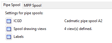
Specify settings for drawings that show pipe spools:
-
ICGD – Click
to select the ICGD to use in pipe spool drawings. -
Spool drawing views – Click
to define views that can be used in pipe spool drawings. See Spool Drawing Views for details. -
Labels – Click
to define label settings for spool drawing views of type 'Plant Modeller'. See Pipe Spool Labeling Settings for details.
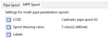
Specify settings for drawings that show multi-pipe penetration spools:
-
ICGD – Click
to select the ICGD to use in pipe spool drawings. -
Spool drawing views – Click
to define views that can be used in pipe spool drawings. See Spool Drawing Views for details. -
Labels – Click
to define label settings for spool drawing views of type 'MPP Plate'. See Pipe Spool Labeling Settings for details.
Spool Drawing Views
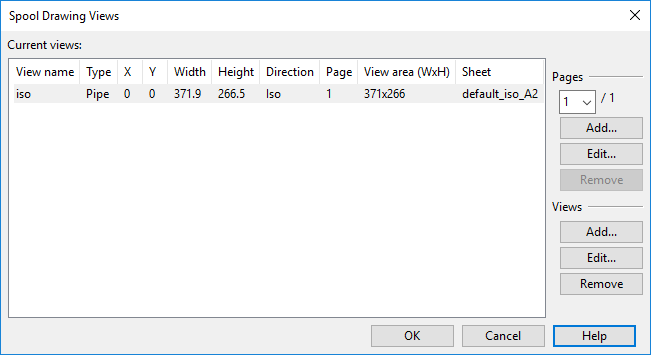
The Spool Drawing Views dialog lists the currently defined spool drawing views. On the right are controls for creating, modifying, and removing spool drawing pages and views.
Pages
Each page is linked to a drawing sheet. You can use a different drawing sheet for every page, if needed. The drawing sheet defines the main elements and properties of the page, such as page size and the size of the view area that contains the drawing views.
In the Pages section, create the number of pages you want spool documents to contain, and define the drawing sheet that each page should use.
- Use the drop-down menu to select a page.
- Add – Adds a new page to the drop-down menu.
- Edit – Allows selecting a drawing sheet for the selected page.
- Remove – Deletes the selected page.
Views display the actual spool drawings.
In the Views section, create the number of views you want the selected page to contain.
-
Add – Opens the Spool Drawings Views dialog for defining a new view for the selected page.
-
Edit – Opens the Spool Drawings Views dialog for editing the settings of the selected view.
-
Remove – Deletes the selected view.
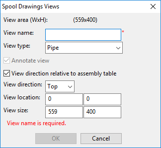
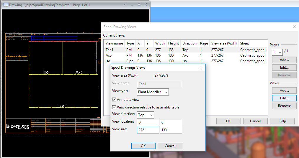
In the Spool Drawings Views dialog, define the view settings.
-
View area (WxH) – Displays the width and height of the view area, as specified in the drawing sheet. The settings for view location and view size are not allowed to position the view outside this area.
-
View name – Enter a descriptive name for the view.
-
View type – Select the type of view to create:
- Pipe – Select to create an unscaled single-line view for pipe spools, similar to the drawings that can be created in the Piping Isometrics & Spools application.
- Plant Modeller – Select to create a view for pipe spools.
- MPP Plate – Select to create a view for the penetration plates of multi-pipe spools.
-
Annotate view – If defining a 'Plant Modeller' type view, you can select this to allow the view to be automatically annotated using the settings described in Pipe Spool Labeling Settings.
The setting is not available for the other view types; 'Pipe' type drawings are always automatically annotated, and 'MPP Plate' type drawings cannot be automatically annotated.
-
View direction relative to assembly table – Select to relate the view direction to how the spools are positioned on the assembly table. If cleared, view direction shows the spools in the same way as in respective work views.
-
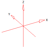
View direction – Select the view direction from which to show the spools, in relation to either model coordinates or the assembly table. For example, 'Top', 'Axo', or 'Iso'.
-
Axo means perspective projection where the drawing is rotated 30° from the XY plane, the angle from the X axis is rotated by -120°, and the view direction is as shown below.
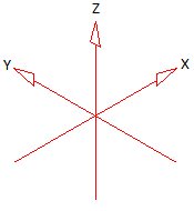
-
Iso means isometric projection where the drawing is rotated so that the angle between all axes is 120° and the view direction is as shown below.
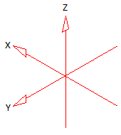
-
Iso1 means isometric projection where the drawing is rotated so that the angle between all axes is 120° and the view direction is as shown below.
-
-
View location – Specify the location of the view as X and Y.
-
View size – Specify the width and height of the view.
Pipe Spool Labeling Settings
Note: These settings are only applied to drawing views of type 'Plant Modeller' or 'MPP Plate'. See Spool Drawing Views.
Define these settings to select labeling styles for pipe spool drawings or multi-pipe penetration plates used by pipe spools. The title of the dialog is either 'Pipe Spool Drawings Labels' or 'MPP Spool Drawings Labels', depending on which type you are setting up.

Labeling style – Select the general labeling style to use.
Labeling style labels – Select which of the following label types to use and what is their labeling style:
- Field weld label – Shows labels to indicate locations that require field welds or contain user-defined extra lengths.
- Flange type label – Shows the flange type in a label.
- Turn angle – assembly table – Shows the rotation angle in degrees from base direction. A positive value indicates clockwise rotation.
- Turn angle – model – Shows the rotation angle in degrees from standard orientation. A positive value indicates clockwise rotation. If the value is 0, then the flange is at standard orientation regarding the direction out of the gasket face.
- Bend part label – Shows labels to indicate pipes that require bending.
- Page label – Shows the page number.
- Bent with flange label – Shows labels to indicate flanges that must be welded before bending the pipe.
- Bent without flange label – Shows labels to indicate flanges that must be welded after bending the pipe.
- Bending tail label – Shows labels to indicate pipe parts that are the tail part in the bending process.
- Bending head label – Shows labels to indicate pipe parts that are the head part in the bending process.
View direction specific labels – Select which of the following view-direction specific labels to use and what is their labeling style:
- Draw set back information label – Select which views can show set back information labels.
- Draw view seam label – Select which views can show seam labels.
- Draw assembly point label – Select which views can show assembly point labels.
- Draw axis marker – Select which views can show axis mark labels.
- Draw dimensions – Select which views can show dimension labels.
Weld Drawing
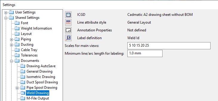
In the Weld Drawing settings, you can specify how Plant Modeller generates weld drawings as described in Document.
-
ICGD – Select the ICGD to use for controlling the creation of weld drawings.
-
Line attribute style – Select the default line attribute style to use when the program creates a plan view for a weld document.
-
Annotation Properties – Select the default annotation properties to use when the program creates a plan view for a weld document.
-
Label definition – Select the label definition to use for welds when views are annotated in weld drawings.
-
Scales for main views – Specify what kind of view scales the program should try when creating a plan view for a weld document.
-
Minimum line/arc length for labeling – Specify the minimum length for lines and arcs in labels shown in weld drawings.
M-File Output
To be able to generate cut lists, during m-file processing Plant Modeller should be able to generate m-records that contain the three tags that are used to sum and compute row mass: len, are, and qty.
To enable summing entries that have for example the same length, the lengths in the m-file need to be output with a fixed number of decimals.
Note: The %g format cannot be used because it tries to output values as accurately as possible.
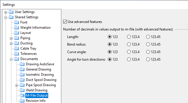
In the M-File Output settings, you can specify the following options.
Use advanced features – This option controls whether advanced features are used with bill-of-material processing. These include:
- Ability to print out values with a fixed number of decimal places.
- The same record can contain all quantities: len, are, and qty.
- Duct length is output as 'len' instead of 'dle'.
When Use advanced features is enabled, you can select how many decimals to use—none, one, or two—when values that specify length, bend radius, curve angle, or angle for turn directions of flanges are output to m-file.
When m-record for a duct is output and new features can be used then 'dle' is replaced with 'len' and 'fii' ouput with specified precision. Also additional materials for frame joints are output so that the same record contains both 'len' and 'qty'. If new features are not enabled then each additional material entry is output to a separate record.
M-files for duct spool drawings do not contain additional material needed in connections, such as cleats and outer corners. They contain only material that is needed for prefabrication.
When values are obtained via PM_GET_OBJDATA()/get_mrecord_of_object(), then these formats are not used but instead output values will be as before.
Plant Modeller has started to generate m-files with records that contain both length (len) and pieces (qty) tags. These are found in additional material records that describe frame joints in thin sheet ducts. The intention is to be able to generate cut lists to duct spool drawings. In cut lists one row may have several items with the same length.
- The first problem is that if a record in m-file contains both pieces and length, then summing in ICGD is not correct, and neither is the computation of row mass.
- The second problem is with columns that are classically used to show either length, area, or pieces in one output column. This works if a data record contains only one of these tags. If, however, a record contains several of these tags, then the output is a simple concatenation of output strings and is not readable but confusing.
- The third problem is that with current ICGD processing you cannot create cut lists—lists that do not sum the len field when rows are summed. It should count pieces and then dump the length and pieces separately.
The solution to the first problem is to deal with the potential 'qty' tag in the input records. If that is present then computation of totals (len, are and rowmass) takes the given 'qty' into account. If both 'len' and 'are' tags are present then mass computation takes place only once. Normally there is no risk with summing the mass twice since a pid should have only one type of unitmass. Anyhow, mass computation is prepared to deal with badly defined dimtables ie. having both areamass or lengthmass.
The second problem is solved in a heuristic manner and works for most of the cases. Namely code that prints tables or fills text rows in sheets recognizes columns that are using the classic combined output column technique. Column is a combined column if:
- Format is '%s%s%s' and all three tags are present in data requests.
- Format is '%s%s' and two of the tags are present in data requests.
In the input record contains more than of the target tags then only one tag will be output. Order of precedence is 'are', 'len' and 'qty'.
The third problem is solved so that ICGD processing knows if a cut list is to be generated. This is signaled by having 'len' tag as part of the summing rule. This means that 'len' has to appear both in sorting rules and summing rules. Only the latter is checked to see if cut list is to be generated. In that case 'len' tag is not summed, but contains the value of 'len' tag from the last record that was summed to the output record. If a record has no 'qty' tag then it is assumed to be 1. In this case 'qty' in the output record would contain the number of records that were summed. Thus in the output we can show how many pieces there are with a given length.
Plant Modeller has not so far created m-files that contain both 'len' and 'qty' tags in one record. However, if there are script-generated m-files from older software versions, those might have these and the result is that Plant Modeller will take these 'qty' values into account and that shows in the totals—both in total length and row-mass.
Below is an excerpt from an ICGD definition that creates a cut list. Notice that in report formats and data tables in drawing sheets that show a cut list you cannot use a combined column, but 'len' must be output to a separate column than 'qty'.
/* BEGIN_SELECTION_RULES */
len; 1; 1e20; /* select records with len */
are;!1; 1e20; /* but ignore ducts (in 6.1 ducts may have "len" tag along with "are" tag) */
;
/* END_SELECTION_RULES */
/* BEGIN_SORTING_RULES */
DE; 2;
DD; 2;
ST; 2;
len; 1; /* sort into descending order */
;
/* END_SORTING_RULES */
/* BEGIN_SUMMING_RULES */
DE;
DD;
ST;
len; /* signals that we want to create a cut list. */
;
/* END_SUMMING_RULES */
Revision Info
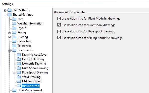
In the Revision Info settings, the following options are selected by default. This means that each time a document is published, revision information is stored. Furthermore, the next time the user opens the document, they are prompted to choose whether to create a new document revision. If you prefer not to have revision information for your documents, clear these options.
- Use revision info for Plant Modeller drawings
- Use revision info for Duct spool drawings
- Use revision info for Pipe spool drawings
- Use revision info for Piping isometric drawings
Hole Management
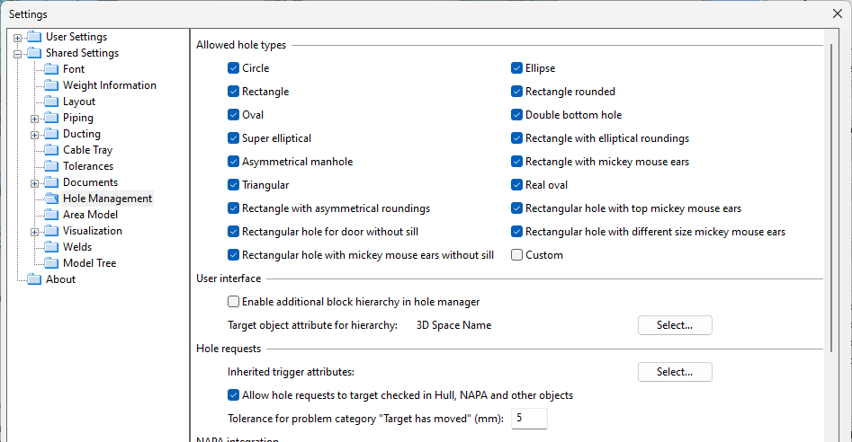
In the Hole Management settings, you can specify the following options for the Hole Manager tool.
-
Specify which Hole types can be used when creating hole requests in the project. Notice that not all hole types are supported in all integrations to other systems. Selecting the Custom option enables the Properties of Hole Request dialog to retrieve hole dimensions from custom shapes modeled as a single sweep.
-
Enable additional block hierarchy in hole manager – Select this option to arrange hole requests according to a specified target object import group attribute. The setting can be used when the target objects are imported from a third-party program (not needed with CADMATIC Hull or NAPA Steel).
-
Target object attribute for hierarchy – Click Select to define which attribute to use for arranging hole requests.
-
Inherited trigger attributes – Click Select to define which attributes hole requests should inherit from their trigger object. This can be used to provide additional information to the hull designer. For example, a door that requires a hole can provide the curve profile or opening type via attributes.
-
Allow hole requests to target checked in Hull, NAPA and other objects – Select this option to allow hole requests to be created when the target object is checked in (not owned by, for example, a Hull Agent).
-
Tolerance for problem category "Target has moved" (mm) – Specify how far the target object can be from the origin of the hole request before the hole request is moved to the 'Target has moved' category. For more information, see Hole request categories.
NAPA integration allows custom hole shapes. In this case, validity checks are not performed. The designer can edit the boundary curve of the hole request, and it is formed using a single sweep.
-
Hole request output format – Select whether to include the hole geometry in the hole request. For example, custom holes should include the geometry in the request.
-
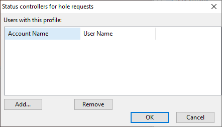
Use manual status control to accept or reject hole requests – Select this option to allow manual status changes in hole requests that target NAPA objects. If selected, the Hole Manager tool shows additional controls to the users defined in the Manual Status Control setting below, allowing them to accept and reject requests, to enter status comments without changing the hole request status, and to edit user-defined attributes assigned to the 'Hole Request Response' COS object type. For more information, see Manual status control.
-
Click Status Controllers to specify which user accounts are allowed to change the status of third-party hole requests manually. Normally, manual status control is used for target objects not managed via CADMATIC Hull or NAPA integration, but it can also be enabled for objects created in NAPA.
Area Model
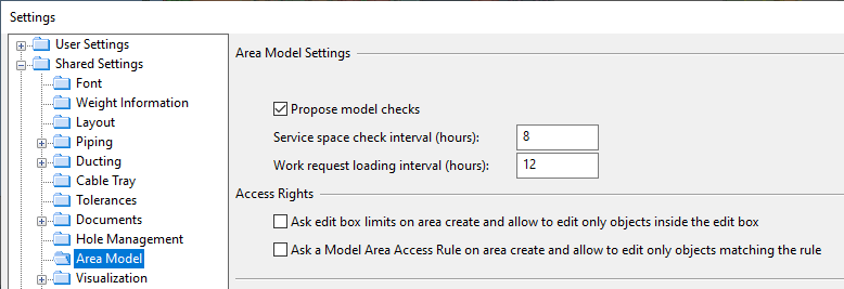
In the Area Model settings, you can specify the following options.
Area Model Settings
These settings are used to schedule area model related checks.
- Propose model checks – If selected, designers are automatically prompted to run a check to validate the area model ("Do you want to check your model now?").
- Model check interval (hours) – Specify the interval for validating the area model.
- Service space check interval (hours) – Specify the interval for scanning all objects for service space synchronization issues. There is also a time stamp file in directory Site/pm that times these checks and synchronizes checks amongst all sessions that can perform actions on objects that are not checked out to anybody but are owned by the current COS server.
- Work request loading interval (hours) – Specify the interval for checking if there are new work requests. You can also change this value in the Save dialog, as described in Saving the area model.
Access Rights
These settings define whether access rights are to be enforced in the project. When these settings are enabled and the user checks objects out or in, requests or relinquishes object ownership, or saves the area model, the program checks whether the user is allowed to perform this operation. If there are conflicts, depending on the command, the user may have the choice to continue the operation with only the non-violating objects or the whole operation may have to be aborted.
Important: These settings are recommended to be set before a project starts. If users have existing areas with checked-out objects and you enable access right restrictions, the users might not be permitted to check in the objects.
-
Ask edit box limits on area create and allow to edit only objects inside the edit box – If selected, users must define the limits of the 3D box inside which they will work, as described in Set model area access rights and save.
-
Ask a Model Area Access Rule on area create and allow to edit only objects matching the rule – If selected, users must select a Model Area Access Rule that specifies what kind of objects they are allowed to edit in the area where they work, as described in Set model area access rights and save.
Project administrators can create these access rules as described in Access rights.
Visualization
Faceting Accuracy
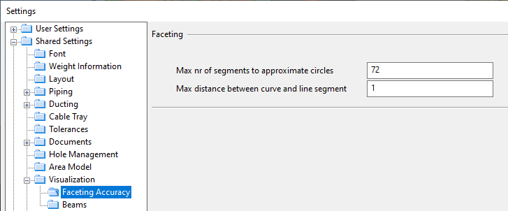
Faceting refers to the process of approximating a smooth surface with a set of planar faces. In the Faceting Accuracy settings, you can set the accuracy for faceting smooth surfaces in 3D primitives of type 'Surface of revolution' or in 3D models created by shape scripts.
-
Max nr of segments to approximate circles – Specify the maximum number of line segments in polylines that the system will use to approximate any circle (4-144).
-
Max distance between curve and line segment – Specify the maximum deviation between a curve and the approximating polyline (0.5-20).
Beams
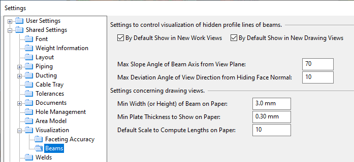
Below you can see some pictures of a U-beam (channel). In wireframe views you can see dashed lines that show hidden profile lines.

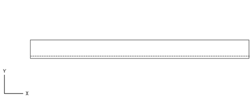
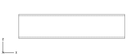
These hidden profile lines are hidden by the beam itself, not by other objects. These hidden lines are treated as center lines. They are NOT treated as hidden edge lines which in turn are lines that are hidden by other objects.
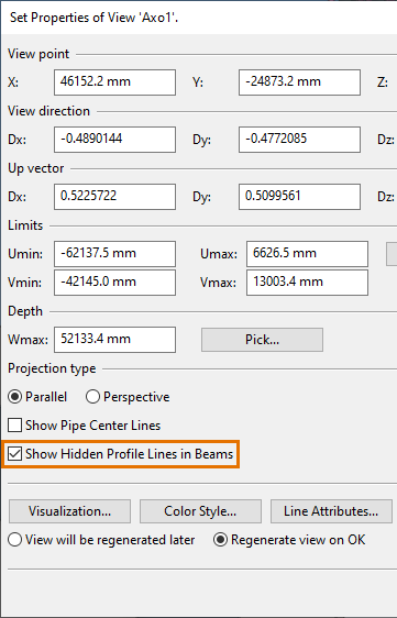
Via Plant Modeller shared settings you can specify new views to have this option enabled by default. There is a separate setting for work views and drawing views. Below you can see the recommended values of all the settings related to hidden profile lines of beams.
Note that hidden line visibility is also definable for each view in the view properties.
Max Slope Angle of Beam Axis from View Plane
Hidden profile lines will be shown for beams that do not deviate more than a given value from the view plane. The default is 70 degrees. This value needs to be relatively big in order to make diagonal beams to show their hidden profile lines at least in principal views.
Max Deviation Angle of View Direction from Hiding Face Normal
Hidden profile line will be shown only if the normal of the hiding face does not deviate too much from the viewing direction. For example if you view the U-beam (channel)from above then the deviation angle would be zero with respect to the top face of the U-beam (channel). Usually this angle should be quite small. The default is 10 degrees.
With work views the above two settings dictate if hidden profile lines of beams are to be shown. Notice that with work views there is no size constraints because you can freely zoom work views and make quite small distances to be visible.
With drawing views you can use size constraints to avoid unnecessarily cluttering the view if the scale is large and it is not even possible to distinguish lines that are close to each other.
Min Width (or Height) of Beam on Paper
If width or height dimension (depends on the viewing direction) of the beam as scaled accordingly is too small as seen in the final drawing then hidden profile lines are not generated for these beams. The recommended minimum value is 1.5 millimeters on paper.
Min Plate Thickness to Show on Paper
With U and L profiles (channel and angle bars) hidden profile line is not generate if the plate thickness that we are about to show is too small as measured on the final drawing. The minimum recommended value is 0.3 millimeters on paper.
Default Scale to Compute Lengths on Paper
When a drawing view is created and its contents is generated before it has been assigned the final scale then a default scale is used when lengths are estimated as millimeters on paper.
If this scale greatly deviates from the final scale of the drawing then you may have to re-visualize the beams that should show these hidden profile lines but currently don’t.
Note: Hint about Line Attribute Styles
When you define Line Attribute Styles then bear in mind that you should have separate rules for beams in order to be able to set proper visual presentation for these hidden profile lines. Remember that internally in the system they are treated as center lines. This same category is currently also used to show center lines of pipes.
Welds
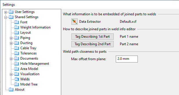
In the Welds settings, you can configure the following options for welds.
-
Data Extractor – This button enables you to select a 3D Publishing Control that specifies the information to be extracted from the welded parts and embedded into the weld that joins them. This embedded information can later be edited in the weld info editor, and it is the edited version that appears in documents that show this information via so-called derived tags.
You need to consider which information available in the model objects cannot be used directly as derived data and therefore needs to be embedded in the weld data. If there is no need to track changes to joined parts and welds do not have to show information on deleted parts, then there is no need to embed this data in the weld. However, if you need to track changes in part data and possibly compare them with the data stored in welds, then this information must be embedded.
Note: Thickness of joined parts is always extracted and presented as embedded data.
-
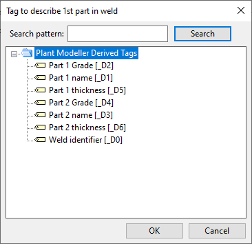
Tag Describing 1st Part, Tag Describing 2nd Part – These buttons allow you to select derived tags that describe the parts joined by a weld. Typically, you have a tag that identifies the first part (an outfitting part) and the second part (an outfitting or hull part). The effect of these tag selections becomes visible in the weld info editor. A dialog opens where you can select one of the derived tags.
-
Max offset from plane – This value is used when a weld path is constructed from a boundary curve obtained from a model object. In an ideal situation, the boundary curve is in complete contact with the weld plane in the target part. However, if the first part is slightly misaligned, the boundary curve may not be in contact with the weld plane at every point along the perimeter. If the gap is greater than the value specified here, a gap is inserted into the path. In the weld path editor, these gaps are displayed as dashed lines.
Model Tree

In the Model Tree settings, you can select which group types can define the hierarchy displayed in the Model Tree pane of Plant Modeller.
-
Basic group types – This section lists group types that are predefined in the Group types configuration.
-
User-defined group types – This section lists group types that your organization has added to the Group types configuration.
-
WBD group types – This section lists special group types that CADMATIC Hull integration creates and stores in a User data object. These group types always have a 'WBD_' prefix, and they allow objects exported from Hull to Outfitting to be displayed in the model tree according to the hierarchical Work breakdown structure defined in Hull.
Note: Even if a group type is not enabled here, the user can still use the model tree to create new groups of that type and manage the objects included in those groups. The tree simply does not display that group type as a separate collection.
Sister Project
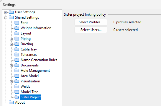
In the Sister Project settings, you can configure the following options.
Sister project unlinking policy / Sister project linking policy
Specify who is authorized to unlink and link sister project objects using commands found in, for example, the Sister project management menu or the Document browser.
You can assign this authorization based on user profiles and/or user accounts, thereby providing this functionality to those who require it and avoiding unintentional actions by others.
-
Select Profiles – Opens a dialog for selecting which User Profiles can unlink or link sister project objects.
This method grants permission to all those whose user account is included in the selected user profile.
-
Select Users – Opens a dialog for selecting which User Accounts can unlink or link sister project objects.
This method grants permission only to the specified users.
Note these additional requirements for the user profile of a user who is to unlink or link sister project objects:
-
For both unlinking and linking, the user profile must have the 'Create' and 'Modify' permissions for the 'Sister Project Export List' object type. For general information on object types, see Object Types.
-
For linking, the user profile must be included in the Modify databases with access control policy of the COS server if the library database is configured to use Policy control.