Edit

On the Layout tab, the Edit group includes the following tools.
Move

You can move a structural component or equipment to another location. If the component has a hole request, the tool also tries to update the location of the hole request.
Do the following:
-
Select Layout tab > Edit group > Move.
-
Select the object to be moved and press Enter.
-
Pick a base point for the move.
-
Start moving the object toward its intended location. You can also use these context-menu commands:
-
You can perform incremental moves with Accept point (Space, click) and undo moves with Undo (U).
-
You can change the base point with Set base point (B).
-
You can toggle the preview animation on or off with Show animation (Shift+K).
-
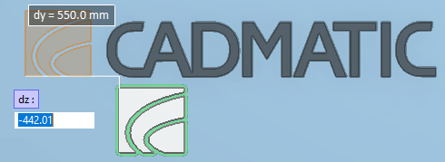
You can restrict cursor movements with the floating distance fields [dx = ] [dy = ] [dz = ]. You can toggle these input fields on or off with Use direction assistance (Shift+O) and activate them for editing with Ctrl+Tab. If you edit a distance value and press Enter, then that distance/direction becomes fixed and the object can only move in directions that are not fixed.
-
You can restrict cursor movements by enabling Navigate > Ortho (F8). When ortho is enabled, the cursor can only move from the base point to one axis direction at a time.
-
-
Pick the new location of the base point.
-
Press Enter to complete the move.
-
If you are prompted that the tool could not update all hole requests that are related to the changed objects, you must run the Update from trigger command in the Properties of Hole Request dialog of Hole Manager.
Rotate

You can rotate a structural component or equipment around any axis. If the component has a hole request, the tool also tries to update the location of the hole request.
Do the following:
-
Select Layout tab > Edit group > Rotate.
-
Select the object to be rotated, and press Enter to accept the selection.
-
Pick a base point for the rotation.
-
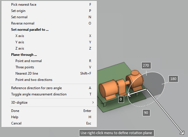
Define the rotation axis:
-
Select a main axis by clicking the center of the selection wheel or using the Change rotation main axis (O) command.
-
Select a custom axis by pressing P and defining the axis direction using context-menu commands.
-
-
Define the amount of rotation:
-
Use the mouse or the arrow keys to rotate the object.
-
Use the Enter rotation angle (Alt+R) command to type the rotation angle.
-
Use the Align to coordinate axes (Alt+A) command to align the object with the coordinate axes.
-
-
Press Enter to accept the rotation.
Delete

You can delete a structural component or equipment from the model. If the component has a hole request, the tool also tries to delete the hole request or to set it to deleted state.
Do the following:
-
Select Layout tab > Edit group > Delete.
-
Select the object to be deleted, and press Enter to complete the deletion.
Change system

You can change the system of model objects.
Do the following:
-
Select Layout tab > Edit group > Change system.
-
Select the model objects whose system you want to change, and press Enter to accept the selection.
-
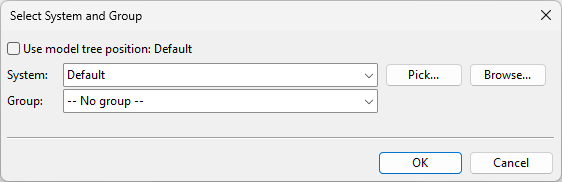
In the Select System and Group dialog, select the system and group to use, and click OK.
-
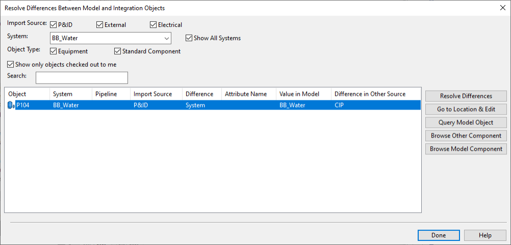
If the model object is linked to any integration objects, the Resolve Differences Between Model and Integration Objects dialog opens, showing that there is now a difference in the system assignment. You can find more details on this dialog in Compare objects. Click Done.