Check / Change
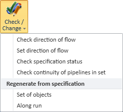
On the Piping tab, in the Edit group, the Check / Change menu includes the following tools.
Check direction of flow
You can view the flow direction of pipe runs.
Do the following:
-
Select Piping tab > Edit group > Check / Change > Check direction of flow.
-
Pick one or more piping parts from the model, and press Enter. The Browse Direction of Flow dialog opens, listing the pipe runs of the picked parts and information about them.
-
Select a pipe run from the list. The object is highlighted in the model, and arrows indicate flow direction.
If you are not sure which pipe run to select from the list, you can click Locate, pick a pipe part from the model, and the respective pipe run gets selected in the list.
-
Use the command buttons on the right to query or browse the head or tail of the selected pipe run:
-
Query Head, Query Tail – Opens the Object properties dialog to display information about the head or tail part (a flange, for example) of the pipe run.
-
Browse Head, Browse Tail – Allows browsing the model, with the cursor placed at the head or tail of the pipe run.
-
-
Click Close to close the tool.


If you observe incorrect flow directions in the model, use the tools described in Set direction of flow to make the necessary changes.
Set direction of flow
You can view or change the flow direction of pipe runs. See also General flow direction rules.
Do the following:
-
Select Piping tab > Edit group > Check / Change > Set direction of flow.
-
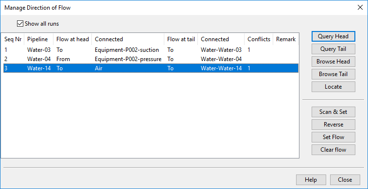
Pick one or more piping parts from the model, and press Enter. The Manage Direction of Flow dialog opens, listing the pipe runs of the picked parts and information about them.
-
Select a pipe run from the list. The object is highlighted in the model, and arrows indicate flow direction.
-
Use the upper command buttons on the right to query or browse the head or tail of the selected pipe run, as described in Check direction of flow.
-
Use the lower command buttons on the right to manage the flow directions of the selected pipe run:
-
Scan & Set – Starts an interactive tools that prompts you to set each flow direction in the selected pipe run by clicking the two-headed arrow.
-
Reverse – Reverses all flow directions in the selected pipe run.
-
Set Flow – Shows the flow direction of the selected pipe runs and allows you to change their flow direction, one connection node or an entire run at a time.
-
Set flow direction for a single connection point:
-
Pick the connection point whose flow direction you want to change, and accept the selection.
-
Press Esc, and then select the new flow direction by clicking the two-headed arrow.
-
Press Esc to return to the Manage Direction of Flow dialog.
-
-
Set flow direction for a pipe run:
-
Pick the connection point at one end of the run, and press Enter.
-
Pick the connection point at the other end of the run, and press Enter.
-
Select the new flow direction for the whole run by clicking the two-headed arrow.
-
Press Esc to return to the Manage Direction of Flow dialog.
-
-
-
Clear Flow – Shows the flow directions of the selected pipe run with thin red arrows. Pick the connection point whose flow direction information you want to remove, and accept the selection.
-
-
Click Close to close the tool.


Check specification status
Select Piping tab > Edit group > Check / Change > Check specification status to review the specification status of a set of piping parts and their insulation. You do not need to check out the objects for this.
The Spec state of parts dialog opens, listing the parts.
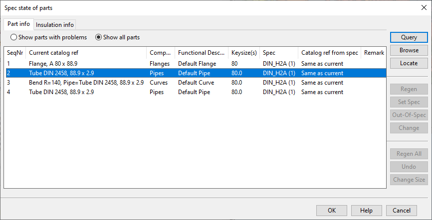
You can select to show all parts or just the parts with problems. Selecting a part highlights it in the model.
Note: Out-of-spec parts whose P&ID status is "Linked" are not reported as problems even if the pipeline does not allow out-of-spec parts. In the Show all parts view, these parts have the remark "Part is specified by Diagram."
You can use the following commands:
-
You can click Query to show the object properties.
-
You can click Browse to start browsing the model at the selected part.
-
You can click Locate to pick a pipe part from the model so that it gets selected in the list.
Note: The other buttons are enabled when using the Regenerate from specification: Set of objects tool.
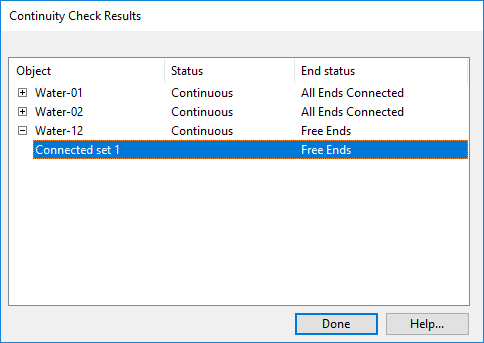
Check continuity of pipelines in set
Select Piping tab > Edit group > Check / Change > Check continuity of pipelines in set to check whether the ends of a set of pipelines are connected.
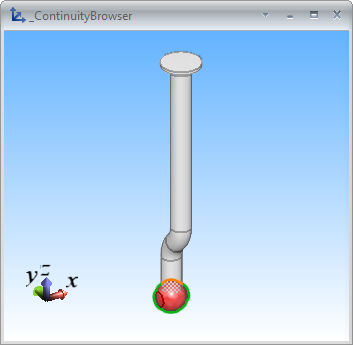
The Continuity Check Results dialog opens, listing the selected pipelines and showing whether they are connected or have free ends. When you select a pipeline from the list, a separate view window shows the pipeline and indicates the free ends, if present. Click Mark Terminator to designate the end as a non-free end.
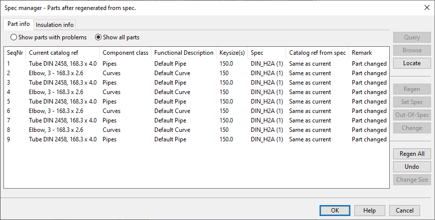
Regenerate from specification: Set of objects
Select Piping tab > Edit group > Check / Change > Set of objects to regenerate piping parts so that they match their specifications. To use this tool, the objects must be checked out to you.
After starting this tool, first pick the parts to be regenerated and press Enter to accept the set. The Spec manager dialog opens, listing the parts.
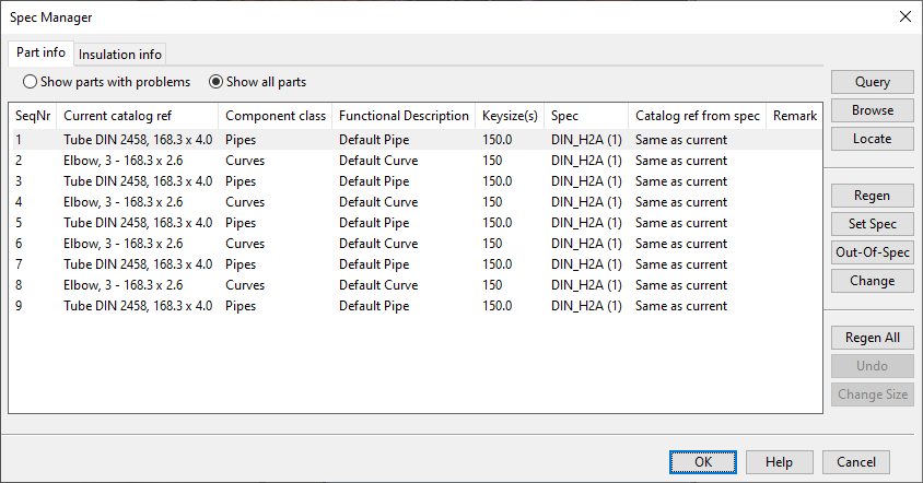
You can use the following commands:
-
Regen – Regenerate the selected parts.
-
Set Spec – Set a new specification for the selected parts.
-
Out-of-Spec – Mark the selected parts to be out-of-spec parts.
-
Change – Change the catalog reference of the selected parts.
-
Regen All – Regenerate all the parts.
-
Undo – Undo the latest change.
Use either Regen or Regen All to regenerate the parts.
You are prompted if some of the parts are no longer compatible with their neighbors or if regeneration failed for some parts.
You can select to show all parts or just the parts with problems. See the Remark column for details on each part.
Parts with problems can have these remarks:
-
"Regen failed for part." – Part could not be regenerated.
-
"Not compatible with neighbours" – Part is not compatible with its neighbors.
Other parts can have these remarks:
-
"Part changed." – Parts was regenerated and changed in the operation.
-
"Part has no line defined." – Part is not assigned to a Pipeline.
-
"Part is specified by Diagram." – Out-of-spec part whose P&ID status is "Linked". (These parts are not listed as having problems even if the pipeline does not allow out-of-spec parts.)
-
"Related hole requests require update." – Part has a hole request that could not be updated because it is not checked out to you. You must run the Update from trigger command in the Properties of Hole Request dialog of Hole Manager.
Insulation can have these remarks:
-
"Insulated by neighbouring part"
-
"Insulation for this type of parts is currently not supported"
If the changed parts have hole requests, the tool also tries to update the dimensions of the hole requests.
Regenerate from specification: Along run
Select Piping tab > Edit group > Check / Change > Along run to regenerate one or more consecutive pipe runs so that they match their specifications. To use this tool, the objects must be checked out to you.
After starting this tool, pick the first part and accept the selection, then pick the last part and accept the selection. All pipe runs between the selected parts are regenerated.
If the changed parts have hole requests, the tool also tries to update the dimensions of the hole requests.
General flow direction rules
There are some general rules on how flow direction is handled when pipes are edited:
-
At the start of a pipe flow direction is IN, and at the end of the pipe it is OUT.
-
If component model specifies flow direction, for example when pipe is routed to either the suction node or the pressure node of a pump, then the direction cannot be changed in the model.
-
Flow direction is looked up from the nearest connection, not from the end or start of the run.
-
Loading pipe objects from MDL does not set flow direction unless it is explicitly specified in the MDL data. Also the header of MDL files must state that the MDL has been created with Plant Modeller version 5.3 or newer.
These situations have special rules for handling flow direction:
Route pipe | Cut pipe | Join pipe | Spec status
Route pipe
-
If the connected ends do not specify flow direction, the start of the pipe is set to IN, and the end of the pipe is set to OUT.
-
At the head of a branch flow direction is set to IN, and at the tail of a branch it is set to OUT.
-
If routing starts from a connection point where flow direction has not been set, it will be set to OUT, if the object that the connection point belongs to is editable.
-
If routing ends at a connection point where flow direction has not been set, it will be set to IN, if the object that the connection point belongs to is editable.
Cut pipe
-
The end of a head pipe inherits flow direction from the end of the original pipe.
-
The start of a tail pipe inherits flow direction from the start of the original pipe.
Join pipe
-
The new pipe inherits flow direction from the pipes that are joined.
Spec status
-
Flow direction, if specified, may dictate how the part can be oriented.
-
Attempt to set flow direction is made at each connected connection point of the component where flow type has not been fixed by component model.
-
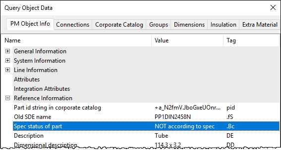
You can see the overall spec status of a part in Object properties, in the Reference Information section.
-
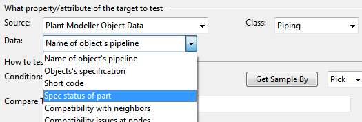
Spec status of part can be used as an operand in a selection test.