Object properties
The Object Properties dialog displays detailed information about the selected model object, model group, 3D space, or attribute. The number of tabs displayed in the dialog depends on the type of the object and the data that is available to the object. These buttons are displayed at the bottom of the dialog:
-
COS Properties – Opens the COS properties of the object; see COS Object Properties for details.
-
Pick Object – Allows you to pick another model object whose properties you want to see.

Tip: You can also use the dockable Properties pane to view object properties.
Opening the Object Properties dialog
The way you access the Object Properties dialog depends on the type of the entity.
Object properties of model objects
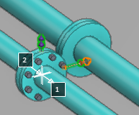
To open the Object Properties dialog for a model object, select the Query or Query object command of the tool you are using, pick the required object, and press Enter.
Object properties of groups
To open the Object Properties dialog for a group:
-
Pick the required model object from a work view, right-click the view and select Get group from the context menu.
-
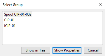
In the Select Group dialog, select the required group from the list and click Show Properties.
Object properties of attributes
To open the Object Properties dialog for an attribute:
-
Pick the required model object from a work view, right-click the view and select Get attribute from the context menu.
-
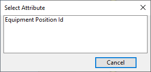
In the Select Attribute dialog, click the required attribute.
Object properties of a named entity
To open the Object Properties dialog for an object or group whose name you know:
-
Right-click a work view and select Search by name (N) from the context menu.
-
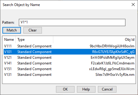
In the Search Object by Name dialog, specify the search pattern and click Match, then select the required object from the search results and click OK.
Tabs in Object Properties
Object Properties displays tabs that are relevant to the type of the selected object.
PM Object Info | Connections | Component Model | Corporate Catalog | Groups | Dimensions | Insulation | Extra Material | eShare Data | Geometry
PM Object Info

The PM Object Info tab shows the following data about the selected object:
-
General Information – Object type, the identification number of the object in this model, the owner's ID and name, the last modification time, and the visibility level.
 Show/hide details
- 3D Space Name (.ne)
- Coordinate system name (.G8)
- COS object id (.pY)
- Modification time (mot)
- Object coordinate system (.IA)
- Object identification (obi)
- Owner id number (owi)
- Owner info (.rP)
- Type of object (obt)
- Visibility level (.qx)
-
System Information – System name and ID, and all attributes assigned to this particular system.
Show/hide details
- Allow Welds (.CD)
- Allowed interference classes (.nZ)
- Density of flowing material (.p5)
- Object's system name (sys)
- Object's system id number (sid)
- Piping system type (U22)
- Source application (.qL)
- Surface treatment (U19)
- System role (.b0)
- System type (U11)
- Temperature of Flow Medium (i06)
- Use in Diagram (.qM)
- Use in Isometrics (.mg)
- Use in Plant Modeller (.qN)
-
Line Information – Shown for pipelines, cable trays, and duct (HVAC) lines, and includes information such as the name of the pipeline, whether the line can be used in P&ID and Plant Modeller, short code, component class, and functional description.
Show/hide details
- Cable tray (.qz)
- Class/Function (.rQ)
- HVAC line (.rR)
- Id of specification (.pd)
- Insulation required (.kp)
- Name of object's pipeline (pli)
- Object's insulation specification (.k6)
- Object's specification (spc)
- Oidstring of object's insulation specification (.ka)
- Short code (sco)
- Use in Diagram (.qM)
- Use in Isometrics (.mg)
- Use in Plant Modeller (.qN)
-
Attributes – Shows information on attributes assigned to the object in Plant Modeller.
Show/hide details
-
Design slope (.K0) – Can be assigned to groups and piping parts. Value is given as the ratio of vertical change to horizontal change (max ±1/2 or ±0.5). Isometric Checks and Spool Checks can be set to check that the slope value of pipe runs that have geometric slope is at least the same as design slope.
-
Equipment Position Id (.n5)
-
-
Diagram Integration Attributes – Shows information on attributes assigned to the object in P&ID.
Show/hide details
- Equipment Position Id (.n5)
- Instrument function (.J3)
- Instrument location (.J4)
- Instrument measure (.J1)
- Instrument modifier (.J2)
- Instrument Position Id (ipo)
- Requires electricity (.IJ)
- Role in Process (U20)
- Subscript (.J0)
- Superscript (.az)
- Valve Position Id (vpo)
-
External Integration Attributes – Shows information on attributes assigned to the object in an external system.
-
Reference Information – Information such as part ID, description, dimensional description, material, and standard of the catalog part. For equipment and structural components, this section displays information on the GDL component.
Show/hide details
- Author (=0F)
- Category description (=00)
- Check date (U08)
- Compatibility with neighbors (.Bd)
- Component manufacturer (.ez)
- Component type (.eX)
- Connection type (.ey)
- Date (=0G)
- DES (DES)
- Description (.dG) [equipment, structural]
- Description (DE) [cable tray, pipe, air duct]
- Dimension table row (.dH)
- Dimensional description (DD)
- Document Id (dld)
- Equipment Type (eTy)
- GDL (.dE)
- Manufacturer (maf)
- Manufacturer's Type Code (mco)
- Mass missing (U09)
- Material (MC)
- Material class (.ew)
- Material for Equipment (U27)
- Model/series (U00)
- Name of component model (cmd)
- Note (not)
- Old SDE name (.fS)
- Part id string in corporate catalog (pid)
- Plate type (.eb)
- Rating (RT)
- Spec status of part (.Bc)
- Standard (ST)
- Standard page number (stp)
- Standard Checked by (U07)
- Standard Status (U06)
- Supplier (SUP)
- Target industry (.ex)
-
Instance Parameters
-
Type Specific Information – Information related to the object type.
Show/hide details
- Area (are)
- Bending angle (fii)
- Bending machine (.Bk)
- Bending radius of a bend (bra)
- Bent pipe length (bpl)
- Conversion not completed (.Em)
- Description of bending machine (.Bl)
- Diameter at end (.nd)
- Ductpart flange setback at 1st node (.nT)
- Fabrication method (mth)
- Height (dh1)
- HVAC duct cross-section (.mm)
- HVAC model as hollow (.mo)
- HVAC modeling category (.ml)
- HVAC shape type (.mn)
- Length (len)
- Length of enclosing box for duct piece (dle)
-
Part in bending (.FL)
Possible values:
- Not included – Part does not participate in any bending process.
- Head – The piping part or flange (if welded before bending) at the pipe end where the first bend is made.
- Tail – The piping part or flange (if welded before bending) that is clamped to the bending machine.
- Midsection – Part is not the head or tail of the pipe.
- Bending check needed – Bending check is not up-to-date and must be run to find out the part's relation to the bending process.
- Can't be bent – Bending check has failed.
- Pipe piece length in bent pipe (.FI)
- Pipe piece length required by bending machine (.FU)
- Piping part modeling category (.EW)
- Plate Surface Area (_PA)
- Plate Perimeter (_PB)
- Plate Width (_PW)
- Plate Height (_PH)
- Prefab boundary at bend (.Eo)
- Quantity (qty)
- Section reference point (.qo)
- Type of airduct piece (dt)
- Type of cable tray part (.qm)
- Width (dw1)
-
Spool Check Results
Show/hide details
- Check execution time (.E7)
- Check result for bending (.EE)
- Check result for clearance (.ED)
- Check result for collision (.EA)
- Check result for continuity (.E8)
- Check result for deliver length (.EC)
- Check result for specification (.EB)
- Check result for volume (.E9)
- Check results (.Dz)
- Check result for slope (.K1)
- Check signature (.EG)
- Check signature validity (.EH)
-
Containment Information – Information on the logistics containment of the object.
Show/hide details
- Block (.m1)
- Logistics containment in (.mG)
- Logistics containment in space with id (.mC)
- Outfit area (.lz)
-
Miscellaneous – Information such as group membership path.
Show/hide details
- Color of object {rgb} (.rc)
- Container Validity Score (.nR)
- Diagram status (.En)
- First spool number in duct main document (.bi)
- Flange rotation from standard position (.ER)
- Group membership path (mbp)
- Group was trimmed during import (.CC)
- Import group managed at site (.E3)
- Imported Object Checksum (.r2)
- Imported Object Source Id (.r0)
- IsoDocName (Idn)
- Logistic phase (U0a)
- Name of duct main group (.ba)
- Name of pipe main group (.Cb)
- Name of piping isometric group (Ign)
- Object was trimmed during import (.CB)
- Original Position Info (.k0)
- Penetration Settings Description (.bw)
- Penetration Settings Name (.bv)
- Plate Penetration Settings (_PS)
- Pump Type (pTy)
- Service space defined in Component model (.bY)
- SpoolName (spn)
- Structural Unit (.bj)
Connections

The Connections tab describes the connection points (nodes) of the selected object. The object can be a piping part, standard component, equipment, duct component, or cable tray.
Opening this tab shows connection point labels in the work views, and to make these labels more readable the object is shown in its original color instead of being highlighted. Click Browse if you want to browse the connection points in the model; press Esc to stop browsing.
The Connections tab shows the following data about the nodes of the selected object:
-
Information of Node <number> – Information on the given connection node.
Show/hide details
- Name of node (nod)
- Nominal size (NS)
- Rating (RT)
- X coord of connection (x)
- Y coord of connection (y)
- Z coord of connection (z)
- Face normal's slope angle (fns)
- Face normal's rotation angle (fnr)
- Width axis's slope angle (wxs)
- Width axis's rotation angle (wxr)
- Geometry point at face (.rk)
- Primary face type (.rX)
- Secondary face type (.rY)
- Face connection code (fc1)
- Description of face (ft1)
- Direction of flow (FL)
- Id string of node (nd1)
- Geometry point at connected face (.rl)
- Primary face type of connected face (.rZ)
- Secondary face type of connected face (.ra)
- Face connection code of connected face (fc2)
- Description of connected face (ft2)
- Id string of connected node (nd2)
- Flange rotation from standard position (.ER)
- Flange thickness for bolt length calculation
- Bolt length for tapped holes
-
Joint Material Of Node <number> – Information on the bolt set used by the connection.
Show/hide details
- Bolt set
- Bolt set id
-
Extra Material Of Node <number> – Information on the extra materials of the connection node.
Show/hide details
- Part id string in corporate catalog (pid)
- Old SDE name (.fS)
- Description (DE)
- Dimensional description (DD)
- Standard (ST)
- Material (MC)
- Quantity (qty)
All angles are given in degrees, and rotation angles are measured counter-clockwise from the positive X-axis in horizontal X-Y plane.
Component Model

The Component Model tab shows a detailed report of the component model from which the selected object has been made. The object can be equipment, structural component, standard component, or a 3D space.
Corporate Catalog

Accessing the Corporate Catalog tab opens an object browser window which shows the catalog part size that the selected object refers to. The object can be a piping part, standard component, beam, duct component, or cable tray.
Groups

The Groups tab lists the groups where the object is a member, either directly or indirectly. A group can be one of the following:
- User-defined group. These can be created with Tools > Groups > Create or Add Set.
- Pipeline. The name of the pipeline is shown.
- Duct line. The name of the duct line ("HVAC line") is shown.
- Cable tray. The name of the cable tray line is shown.
-
Group that users cannot define interactively:
- Spool
- Isometry
- Support Location Plan
- Piping Support
- Prim and Sec Supports
- Duct Spool
- Duct Main Document
- Penetration
- Structural Unit
- Phase in Logistics 3Dspace
- Pipe Main Document
Dimensions

The Dimensions tab lists the dimension parameters and parameter values of the catalog part that the selected object refers to. The object can be a piping part, standard component, beam, duct component, or cable tray.
Insulation

The Insulation tab shows information about the insulation of the object. The object can be a piping part, standard component, or duct component.
Extra Material

The Extra Material tab shows information on additional materials such as nuts and bolts that have been assigned to the group of a structural unit. For information on how to assign materials to a group, see Manage.
- To select a group, pick an object from the model, right-click the work view, and select Get group from the context menu. Then select the appropriate group from the list, and Object Properties opens.
eShare Data
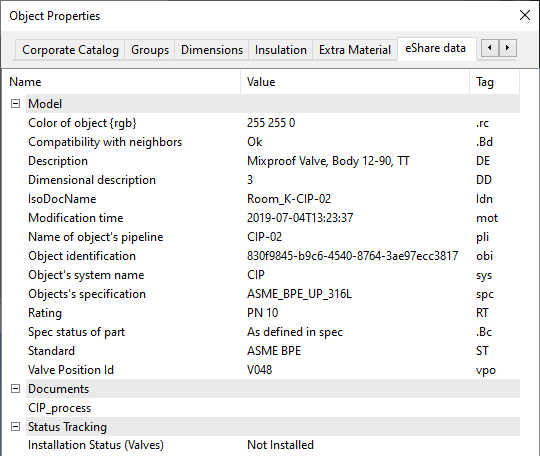
The eShare data tab shows the information that is available for the object in the CADMATIC eShare server that the project is connected to. This information includes the tags that Plant Modeller published to the 3D model and additional fields provided by eShare, such as status tracking values and a list of documents that contain the object.
Geometry
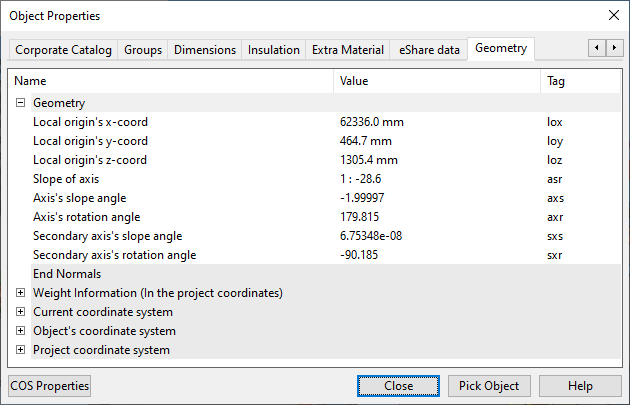
The Geometry tab shows the following data about the selected object:
-
Geometry – Coordinate information and orientation information.
Show/hide details
- Axis's rotation angle (axr) – Axis's rotation angle in positive or negative degrees.
- Axis's slope angle (axs) – Axis's slope angle in positive or negative degrees.
- Axis's slope ratio (asr) – Axis's slope ratio as a positive expression, such as 1 : 100.0
- Length measured along axis (axl) – Axis's length in millimeters.
- Local origin's x-coord (lox)
- Local origin's y-coord (loy)
- Local origin's z-coord (loz)
- Rotation angle around axis (rtx) – Part's rotation around its axis in positive degrees.
- Secondary axis's rotation angle (sxr)
- Secondary axis's slope angle (sxs)
-
End Normals
Show/hide details
- Additional endcut info at end of beam (.kz)
-
Weight Information
Show/hide details
- COG x for operational mass with content (.EK)
- COG y for operational mass with content (.EL)
- COG z for operational mass with content (.EM)
- Content COG x (.p1)
- Content COG y (.p2)
- Content COG z (.p3)
- Content Weight (.p0)
- Mass (MAS)
- Operational mass with content (.EJ)
- X coord of center of gravity (CGX)
- Y coord of center of gravity (CGY)
- Z coord of center of gravity (CGZ)
-
Current coordinate system
Show/hide details
- Coordinate system name (.G8)
- Local origin's x-coord (lox)
- Local origin's y-coord (loy)
- Local origin's z-coord (loz)
- Basis vector X
- Basis vector Y
- Basis vector Z
- Translation
-
Object's coordinate system
Show/hide details
- Coordinate system name (.G8)
- Local origin's x-coord (lox)
- Local origin's y-coord (loy)
- Local origin's z-coord (loz)
- Basis vector X
- Basis vector Y
- Basis vector Z
- Translation
-
Project coordinate system
Show/hide details
- Coordinate system name (.G8)
- Local origin's x-coord (lox)
- Local origin's y-coord (loy)
- Local origin's z-coord (loz)
- Basis vector X
- Basis vector Y
- Basis vector Z
- Translation
COS Object Properties
In the Object Properties dialog, clicking COS Properties opens the COS Object Properties dialog where you can view the COS properties of the selected object. COS properties exist if the object has been saved (updated to COS) at least once.
The dialog has the following tabs.
General
The General tab displays general information that all object types have, such as the date and time when the object was created, last modified, or checked out, as well as the COS IDs of the object.
You can select the ID string from the fields "Object ID" and "GUID" and then press Ctrl+C to copy the ID to the clipboard.

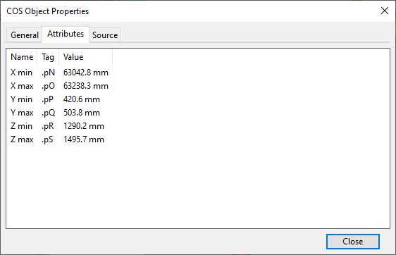
Attributes
The Attributes tab displays object type specific attributes such as the XYZ values of the object's bounding box, Equipment Position Id, and Plant Modeller object ID number.
You can press Ctrl+E to export the attributes to a Microsoft Excel file, as described in Export data tables to Microsoft Excel.
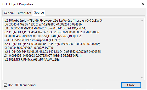
Source
The Source tab displays the source data of the object.
The Use UTF-8 encoding option is selected by default to support the displaying of Unicode characters. Clear the option if you want the source to be shown using Multibyte Character Set (MBCS) encoding.