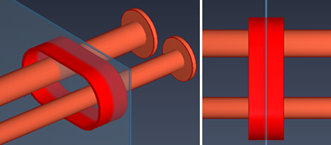
Multi-pipe penetration with sleeve
You can use this command to create a multi-pipe penetration with a common sleeve for pipes passing through a target plate such as a bulkhead or deck.
Prerequisites
-
Common sleeve settings define the nominal pipe sizes that can pass through the common sleeve and specify whether the sleeve is made entirely of plate material or a combination of plate material (straight segment) and a split sleeve part (curved sides).
-
Hull plate material mappings specify the catalog parts used for the plate material and the sleeve.
Do the following:
-
Route pipes through the target plate.
-
Select Piping tab > Penetration group > Insert > Multi-pipe penetration with sleeve.
-
In the Select common sleeve settings dialog, select the settings to use, and click OK.
-
In the 3D model, select the pipes to include, and press Enter.
-
Select the target plate, and press Enter.
-
You are prompted to specify the plate side. This selection does not affect the result—you can select Yes to accept the suggested side or No to select the other side. In both cases, the construction will be symmetrical on both sides.
-
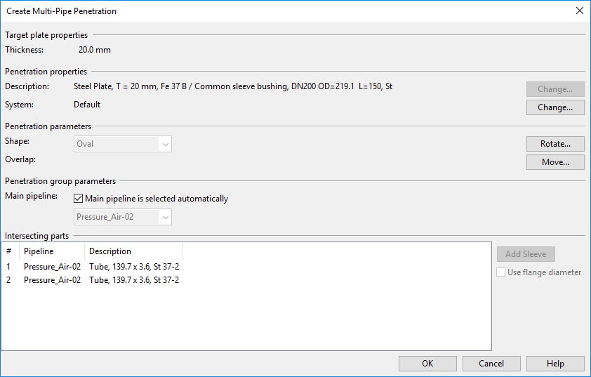
The Create Multi-Pipe Penetration dialog opens, showing information about the target plate, the penetration, and the included pipes.
The tool uses outer diameter, length, and hole clearance values from the selected common sleeve settings, as determined by the penetrating pipe with the largest outer diameter. For example, if common sleeve is constructed for Pipe A (larger) and Pipe B (smaller), the tool selects settings from the common sleeve settings row that matches the nominal size of Pipe A.
When the common sleeve is constructed using plate material and a sleeve part, the sleeve's catalog part size is selected using hull material mappings and the common sleeve settings for the pipe (or flange) with the largest outer diameter. Hull plate material mappings define the sleeve catalog part based on target hull plate material. The sleeve catalog part size is the size of the defined catalog part where the ODsleeve dimension matches the outer diameter value in the selected settings row. From the selected catalog part size, the WTsleeve dimension defines the thickness of the arced parts, ODsleeve defines the diameter of the arced parts, and Lsleeve defines the sleeve length.
-
Specify the penetration settings:
Target plate properties
-
Thickness – Displays the thickness of the target plate. When hull plate material mappings are used, the plate part and sleeve part are selected based on the target plate's material. The penetration plate thickness matches the target plate thickness; if an exact match is unavailable, the next greater thickness is selected. This rule applies to both common sleeves made entirely of the plate material and to straight segments in common sleeves that use a sleeve part for the curved sides.
Penetration properties
- Description – Displays the material selected for the penetration plate. When hull plate material mappings are used, the material is chosen automatically. Click Change to change it.
- System – Displays the system for the penetration. Click Change to change it.
Penetration parameters
-
Shape – Displays the shape of the common sleeve. Click Rotate to rotate the sleeve on the target plate. You are prompted to define a point on the sleeve's width axis and specify the direction of the width axis. The rotation can change the sleeve shape. Rotation cannot be undone.
-
Overlap – (Overlap is not calculated in this context.) Click Move to move the common sleeve on the target plate. You are prompted to define a reference point and its new location. The move action does not affect the sleeve shape. Moving cannot be undone.
Penetration group parameters
- Main pipeline – If Main pipeline is selected automatically is selected, the pipe with the largest Nominal Size determines the penetration's main pipeline. Clear the option to select the main pipeline manually. You can change this later with the Main pipeline of multi-pipe penetration command.
Intersecting parts displays the included pipes. Select a pipe to highlight it in work views and access its options:
-
Use flange diameter – If the pipe has flanges, this option is selected by default to calculate sleeve size from flange diameter. Clear the option to calculate sleeve size from pipe diameter.
-
-
Click OK to create the penetration.
-
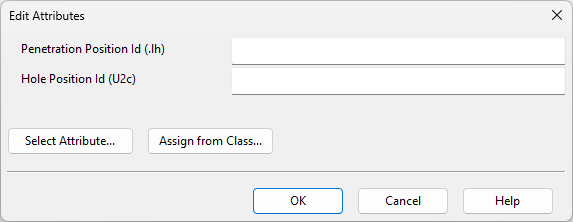
In the Edit Attributes dialog, specify attribute values for the hole request, and click OK.
-
To submit a hole request to hull designers, open the Hole Manager and select Send Request.