Tools
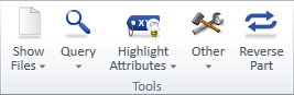
On the Admin Tools tab of the isometric view editor, the Tools group contains the following tools.
Show Files

The Show Files drop-down menu contains the following tools.
Annotation file | DDL file | M file | H file | G file | Revision table file | Weld/Joint file | Profile file
Annotation file
Annotation file opens a dialog that shows the annotation file of the active drawing.
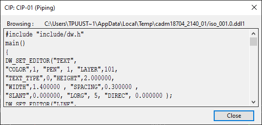
DDL file
DDL file opens a dialog that shows the DDL file of the active drawing.
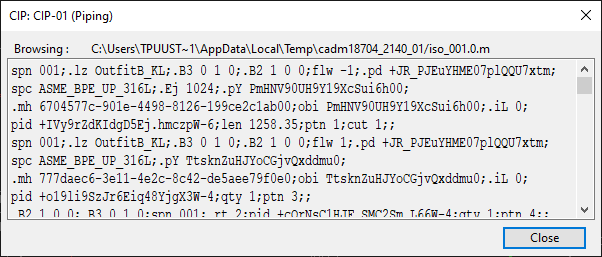
M file
M file opens a dialog that shows the .m file of the active drawing.
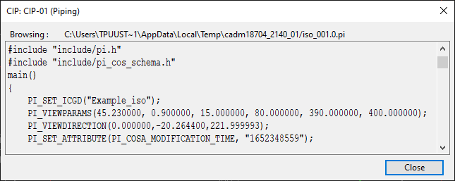
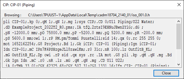
H file
H file opens a dialog that shows the .h file of the active drawing.
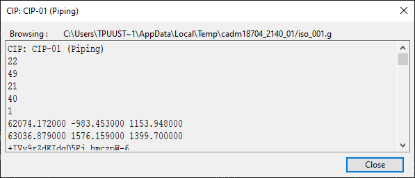
G file
G file opens a dialog that shows the .g file of the active drawing.
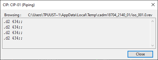
Revision table file
Revision table file opens a dialog that shows the revision table file of the active drawing.
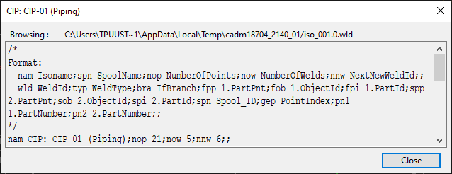
Weld/Joint file
Wel/Joint file opens a dialog that shows the weld/joint file of the active drawing.
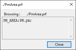
Profile file
Profile file opens a dialog that shows the profile file of the current Plant Modeller area.
Query

The Query drop-down menu contains the following tools.
Part by index | Branch points | Main part | Bent pipe | Extra materials
Part by index
Part by index allows you to specify a part index and then shows the properties of that part.
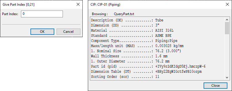
Close the property dialog and click Cancel to exit the tool.
Branch points
Branch points allows you to select a pipe that has branches and then shows the branch points of that part.
Press Esc to exit the tool.
Main part
Main part allows you to select a branch part that has a main part and then shows information about that part.
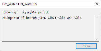
Close the dialog and press Esc to exit the tool.
Bent pipe
Bent pipe allows you to select a pipe that has bends and then shows information about that part.
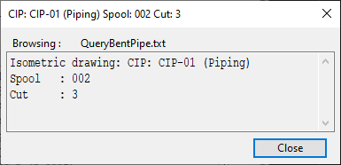
Close the dialog and press Esc to exit the tool.
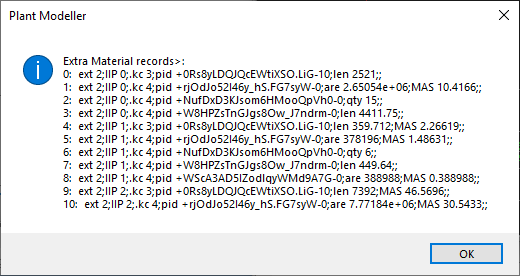
Extra materials
Extra materials opens a list of extra material records.
See also Delete extra material attribute.
Highlight Attributes

You can highlight the parts that have a specific attribute in the active isometric drawing. The Highlight Attributes drop-down menu contains the following attributes:
-
Spool <spn>
-
Part id <pid>
-
Object id <obi>
-
Specification <spc>
-
Bending machine id <bnt>
-
Reference to parent pipe <.ph>
-
Iso cut identifier <.Ej>
-
Part number <ptn>
-
Cut number <cut>
-
Updated parts <Iup>
-
Valve position <vpo>
-
Valve operator label <_op>
-
Instrument position <ipo>
-
Insulation <Iin>
-
Tracing <.kb>
-
End cut at 1st point <Isc>
-
End cut at 2nd point <Iec>
-
Primary line segment <.iL>
-
Secondary line segment <.iM>
-
Instance parameters <.E4>
Select an attribute from the menu to open a dialog that shows which attribute values are found in the active drawing. If you click a specific value in this dialog, the drawing highlights the parts that have that specific attribute value. If you click No tag, the drawing highlights all the parts that do not have that attribute at all.
![]()
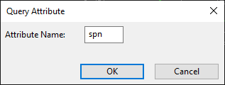
You can also highlight parts that have an attribute which is not listed in the menu. Other attributes can be found by selecting Highlight Attributes > User defined attribute. This opens a dialog where you can enter an attribute tag and then click OK to find the associated parts.
Other

The Other drop-down menu contains the following tools.
List dimensions | Draw line segments | Insert point index label | Insert part index label | Reload 2D symbol library and label definitions | Reload coordinate references | Add/change flow arrow | Delete flow arrow
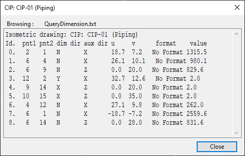
List dimensions
List dimensions opens a list of the dimensions found in the active drawing.
Draw line segments
Draw line segments prompts you to select whether to show point information and then shows line segments in the active drawing.
Insert point index label
Insert point index label allows inserting index labels to the points in the active drawing, such as pipe geometry points, reference points, and end points. Press Esc to stop inserting labels.
Insert part index label
Insert part index label allows inserting index labels to the parts in the active drawing. Press Esc to stop inserting labels.
Reload 2D symbol library and label definitions
Reload 2D symbol library and label definitions reloads the 2D symbol library and label definitions from COS.
Reload coordinate references
Reload coordinate references reloads coordinate references from COS.
Add/change flow arrow
Add/change flow arrow allows inserting flow direction arrows into straight pipes. Click the same pipe again to reverse the direction.
Delete flow arrow
Delete flow arrow allows removing existing flow direction arrows from straight pipes.
Reverse Part

Reverse Part allows you to select a part whose geometry is of type DM_GT_2P and then reverses the direction of that part.