Creating a view
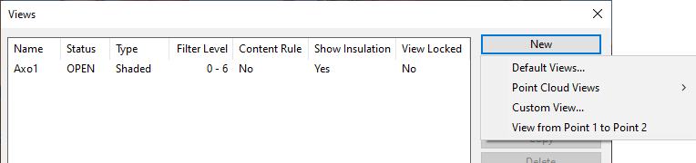
In the Views dialog, the New button opens a menu that contains commands for creating new views.
For a new project, it is usually practical to create some default views that use your model area's limits as the view limits.
Default Views
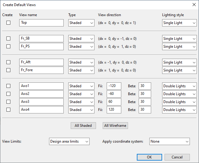
In the Create Default Views dialog opens automatically when you start Plant Modeller for the first time. In this dialog, new work views can be created by selecting the required view properties such as view direction, lighting style, and coordinate system.
There are nine default views with predefined view directions. All views are shaded by default, but you can change the type to wireframe.

Do the following:
-
In the Views dialog, select New > Default Views. The Create Default Views dialog opens.
-
Select the Create checkbox of the views to be created.
-
Enter a unique View name for each view to be created. The view name cannot contain the characters ~ - # and the maximum length is 115 characters.
Note: The name field does not check if such view already exists, but upon creating the view the program asks whether to replace the existing view or cancel the creation so that you can give the new view a different name.
-
In the Type column, select whether to create shaded or wireframe views.
Tip: When working in a shaded view, you can turn the view into a Shaded wireframe view.
-
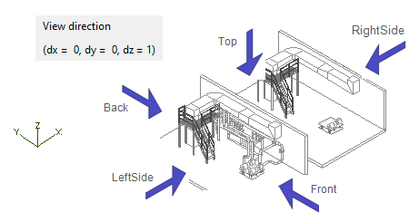
The View direction column shows the view direction of non-axonometric views in reference to the main coordinate axes. For example, the Top view has a view direction (0,0,1) which means that the view shows the model from the direction of the positive Z axis.
For axonometric views, view direction can be adjusted by editing the Fii and Beta values.
-
Select a Lighting style for each shaded view. For non-axonometric views the default is "Single Light", and for axonometric views the default is "Double Lights".
-
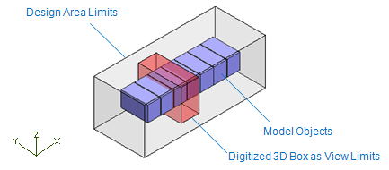
Select View Limits for the views you are creating:
-
Design area limits – Select this option to show the whole model area in the views.
-
Digitize 3D box – Select this option to pick two corner points for a box that defines the view limits.
-
Pick object to views – You can select objects into the views with normal selection rules.
For more information on view limits, see View box.
-
-
Apply coordinate system is set to "None" by default, meaning that the views you are creating are to use the global coordinate system of the project. If your project administrator has defined local coordinate systems, you can set the views to use one of them instead of the global coordinates. For more information on local coordinate systems, see Local coordinate systems.
Point Cloud Views
Creating views to display point clouds or related information such as scanner positions is easy with following three types of default point cloud views with different roles regarding point clouds.
For more information on point cloud view filter properties, see Role of view regarding point clouds.
Orthogonal Shaded
Orthogonal shaded views are created like default views but in addition views are defaulted to shaded and have the Show point cloud in view view filter property on to show all active point clouds in the view.
Tracking
Tracking views are created like default views but in addition views have the Show point clouds in view and Make view follow selected point in bubble view view filter properties on.
Tracking views follow points selected in point cloud bubble views. View visualizes all points inside the filter box of the view.
For tracking views view limits are defined as a filter box with three parameters: length(X), width(Y) and height(Z).
Scanner Map
Scanner map views are created like default views but in addition views have the Show scanners in view and Act as a scanner map view filter properties on.
Scanner maps show the location of each scanner with color coded scanner information.
- Red: scanner is active.
- Yellow: the scanner is inactive.
- Green: the currently active view is a bubble view of the scanner.
Custom View
Custom views can be useful when you need to display some details in a crowded area of the model. They can also be useful for creating cutting views that display the same location from different directions.
Do the following:
-
In the Views dialog, select Create > Custom View.
-
In the Create View dialog, select whether to create a shaded or wireframe view, enter a name for the new view. The view name cannot contain the characters ~ - # and the maximum length is 115 characters.
Then click OK. If a view by that name already exists, you are prompted to overwrite it. The new view is stored in a working copy, meaning that the existing version will not be overwritten until you save the area model.
-
In the Set Properties of View dialog, define settings for the new view, and click OK.
View from Point 1 to Point 2
You can create a set of wireframe views that show a user-defined set of objects from different angles, and then use these views, for example, in Plant Modeller drawings. You can create up to five different views at the same time: a view that faces a user-defined direction, a view from top to bottom, a view from right to left, a view from left to right, and an axonometric view.
The limits of each view are defined by a bounding box that is formed by the visualized objects, the view direction, the up direction, and (optional) user-defined margin.
Do the following:
-
In the Views dialog, select New > View from Point 1 to Point 2.
-
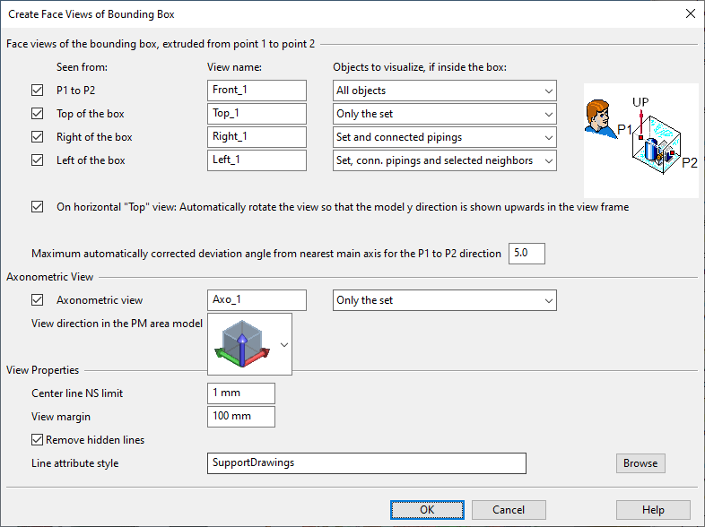
Select the objects that you want to be visualized in the view and press Enter. The Create Face Views of Bounding Box dialog opens.
-
To create a view that faces a specific direction, define the following settings:
-
Seen from – Select whether the view direction is from point 1 to point 2 or from the top, right or left side of the bounding box.
-
View name – Enter a descriptive name for the view.
-
Objects to visualize, if inside the box – Select which of the objects that are inside the bounding box to visualize in the view:
-
All objects – All objects.
-
Only the set – Objects you initially selected into the set.
-
Set and connected pipings – Objects you selected and pipes that are connected to those objects.
-
Set, conn. pipings and selected neighbors – Objects you selected, pipes that are connected to those objects, and additional objects that you will select later on during this procedure.
-
-
On horizontal "Top" view… – Select this option if you are creating a top view and you want the 3D model's Y direction to point upward in the view frame.
-
Maximum automatically corrected… – Define how many degrees the view direction can deviate from the nearest main axis direction. If the deviation is less than this value, the view is aligned with the coordinate axes of the 3D model.
-
-
To create an axonometric view, define the following settings:
-
Make sure Axonometric view is selected.
-
Enter a descriptive name for the axonometric view.
-
Select the view direction of the axonometric view from the menu.
-
Select which objects to visualize in the axonometric view.
-
-
Define the view properties:
-
Center line NS limit – Define the smallest nominal size for showing the centerline of pipes.
-
View margin – Define how many millimeters of extra space to add around the bounding box of the view.
-
Remove hidden lines – Select this option to allow hidden lines to be removed when the view is created.
-
Line attribute style – This option is shown when you are creating a drawing view. Click Browse to select a specific line attribute style for the drawing views to be created.
-
-
Click OK.
-
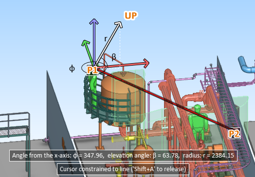
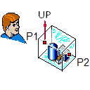
Pick a start point (P1) for the vector that defines the view direction.
-
Pick an end point (P2) for the vector that defines the view direction.
-
Define the up direction of the view. The program tries to select a suitable direction and locks the direction—press Ctrl+A if you want to release the cursor and select another direction. Click or press Space to accept the direction.
-
If you chose to include "selected neighbors" in any of the views to be created, select those additional objects and press Enter.
The specified views are created.