Tips
General tips
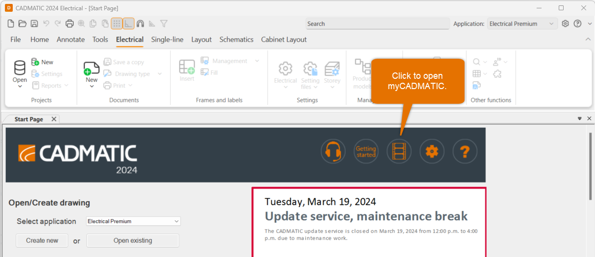
On the program start page at the top, you can find a video button. Click it, and register to myCADMATIC.
After your activation request has been approved, you get access to our video libraries at myCADMATIC.
Do the following:
-
Enter your name and email address, and click Sign up.
-
Check your email for the activation link.
-
Enter your desired password, and click Set password.
-
To have access to all content, click Submit activation request at the top of the page.
-
Enter your customer number and company name, and click Submit. We will send you a confirmation via email, and you can start exploring myCADMATIC.
You can easily edit various general settings for the user interface, automatic saving, grip, file format, reference drawings, etc. Select File > Settings > General settings.
To learn more, see Define general settings.
There are several shortcut keys you can use while working with CADMATIC Electrical. Try these, for example:
-
Ctrl pressed down – Enable/disable snap
-
Shift pressed down – Enable/disable ortho
-
F8 – Rotate symbol according to ortho angle
-
Tab – Change insertion point
-
Shift + right-click – Open a menu of other useful functions
To learn more, see Shortcut keys.
You can open a window called External references to the left side of the screen. You can easily add DWG, DXF, IFC, PDF and many image file formats as reference drawings to a document. After that, you can update, change, hide, lock, etc. reference drawings from there.
Note that you can define a conversion file for DXF and DWG files in File > Settings > General settings > Documents to define default colors for added reference drawings.
To learn more, see Manage reference drawings and Define document settings.
You can add new printers whenever necessary; select File > Settings > General settings > Print. In the Print style table section, you can define line widths for different colors and change the colors if needed.
To learn more, see Define print settings.
Layout tips
When you start a new drawing, Layout will ask about the printing scale (which indeed only affects printing). It is recommended to set the symbol scale factor according to the scale. You can edit these later by selecting Home tab > Modify group > Scale menu.
To learn more, see Scale objects.
The Drawing sheet function on the Layout tab, in the Frames and sheets group allows you to create a layout, print frame and viewport at one go. You can easily define automatic scales for the desired paper sizes, and define marginals and insertion point. Later, you can edit the settings by selecting Edit drawing area from the Drawing sheet menu.
To learn more, see Set and edit drawing area.
For listing functions, select Layout tab > Other functions group > List functions.
To learn more, see List functions.
To open the Wiring window to the left of the screen, select Layout tab > Wiring group > Draw. Then define the wiring style. After indicating the first point, check the useful shortcuts listed to the command line for additional settings for angles, curving settings, etc.
To learn more, see Draw wiring.
Positioning functions are available
To learn more, see Positions.
With the File > Print > Print frames from drawings function, you can select which documents you want to print. Note that you can construct the file names from the printing function with the label values. Otherwise, they will be automatically generated.
To learn more, see Print frames from drawings.
You can open the Electrical and Electrical 2 windows with project trees to the left side of the screen. You can select the kind of objects you want to view from the drop-down menu.
You can use the tree to see all objects in all project documents. Find the desired object (such as a device or a cable), and right-click it to open a menu with available functions. Select Show occurrences from drawing. If the object has multiple occurrences, you can move to the next occurrence with Enter. Finally, close the function with Esc.
To learn more, see Electrical windows and project tree.
When you start creating a new document, you have the option to add it to a project. You can also do this later in the Electrical or Electrical 2 window by clicking the ![]() (Add document to project) button. All project documents communicate with each other. Furthermore, you can see all objects from all project documents in the project tree and the database, and view and edit them freely.
(Add document to project) button. All project documents communicate with each other. Furthermore, you can see all objects from all project documents in the project tree and the database, and view and edit them freely.
To learn more, see Create new drawings and Electrical windows and project tree.
You can start defining project information and settings by selecting Electrical tab > Projects group > Settings. In addition, you can edit the default settings.
To learn more, see Project settings.
Currently, you can have one storey in each drawing. To set up storeys, select Electrical tab > Settings group > Storey. Select the building, and then add new storeys with the ![]() button.
button.
You need to assign the correct file for each storey, and define the storey number and elevation. After this, you can move from storey to storey with the Page Up and Page Down keys. Furthermore, you can draw wiring and cableways from storey to storey. Additionally, the IFC export uses these coordinates to create a complete BIM model of the building.
To learn more, see Storey settings and Export to IFC.
Creating product templates is easy: Insert symbols to a drawing you want to use for creating product templates. In the project, select Product models from the drop-down menu in the Electrical window. Right-click the top node in the project tree (project name), select Create new product model from device, select the desired symbols from the drawing and press Enter. The product models have now been created to the project.
You can edit the product models freely by right-clicking them in the project tree. In addition, you can add or edit any symbols / data fields.
You can insert product model’s devices via the project tree, by right-clicking the product model.
To learn more, see Product models.
Open the database by selecting Electrical tab > Projects group > Open. This opens a full database view of the whole project.
You can view devices, locations, cables, etc. on separate tabs. After you edit values, such as the ID, you need to go back to the drawing side and click the ![]() (Sync changes from database to drawing) button in the Electrical window. If the ID attribute value is visible, you can see the change immediately. If the ID is not visible, hover on top of the object with your mouse to see an information box. Note that you need to save the drawings to get the objects to the database.
(Sync changes from database to drawing) button in the Electrical window. If the ID attribute value is visible, you can see the change immediately. If the ID is not visible, hover on top of the object with your mouse to see an information box. Note that you need to save the drawings to get the objects to the database.
To learn more, see Manage projects and databases in DB Tool.
When you have created objects with 3D symbol equivalence, you can generate an IFC file of all these elements with the Layout tab > 3D and view group > Export to IFC file function. Select the storeys you want to generate to IFC. Also select the objects you want to include. The file is created to the project directory.
To learn more, see Export to IFC.
You can find reporting functions by selecting Electrical tab > Projects group > Reports menu > Reports. You can create, for example, an Excel report of the cables in the project. Select the following:
-
Report type – Cables list
-
Template – (Common) CableList.xls
-
Export to – Excel file
-
Add to project as a project document
Then click OK to create the report to the project folder and make it a project document. Note that you can use filters and sorting to change the list items. You can also create your own templates.
To learn more, see Create reports.
Schematics tips
When you start creating a new document, you have the option to add it to a project. You can also do this later in the Electrical or Electrical 2 window by clicking the ![]() (Add document to project) button. All project documents communicate with each other. Furthermore, you can see all objects from all project documents in the project tree and the database, and view and edit them freely.
(Add document to project) button. All project documents communicate with each other. Furthermore, you can see all objects from all project documents in the project tree and the database, and view and edit them freely.
To learn more, see Create new drawings and Electrical windows and project tree.
Open the database by selecting Electrical tab > Projects group > Open. This opens a full database view of the whole project.
You can view devices, locations, cables, etc. on separate tabs. After you edit values, such as the ID, you need to go back to the drawing side and click the ![]() (Sync changes from database to drawing) button in the Electrical window. If the ID attribute value is visible, you can see the change immediately. If the ID is not visible, hover on top of the object with your mouse to see an information box. Note that you need to save the drawings to get the objects to the database.
(Sync changes from database to drawing) button in the Electrical window. If the ID attribute value is visible, you can see the change immediately. If the ID is not visible, hover on top of the object with your mouse to see an information box. Note that you need to save the drawings to get the objects to the database.
To learn more, see Manage projects and databases in DB Tool.
If you have multiple documents open in the same project, you can continue wires/cables in another document after ending wiring in an empty spot. These references automatically update if they are moved. In project settings, you can define what connection data is shown with the references.
To learn more, see Markings and Wiring reference settings.
If you insert, for example, a contactor with its coils and contacts to different documents, the program automatically creates references. These references will also be updated automatically, as long as the documents are in the same project.
You can import lots of different objects and related data from Excel, and also update existing objects. Open the database by selecting Electrical tab > Projects group > Open. Then on the Functions tab, select Import > Import definition management.
You can then create a new definition mapping Excel columns with our database columns (a correspondence table). With the definition, you can import data from Excel to the database – try to import simple devices with IDs and some related data, for example.
To learn more, see Manage import definitions and import.