|
|
Single-line tab > Other functions group > Loop diagram |
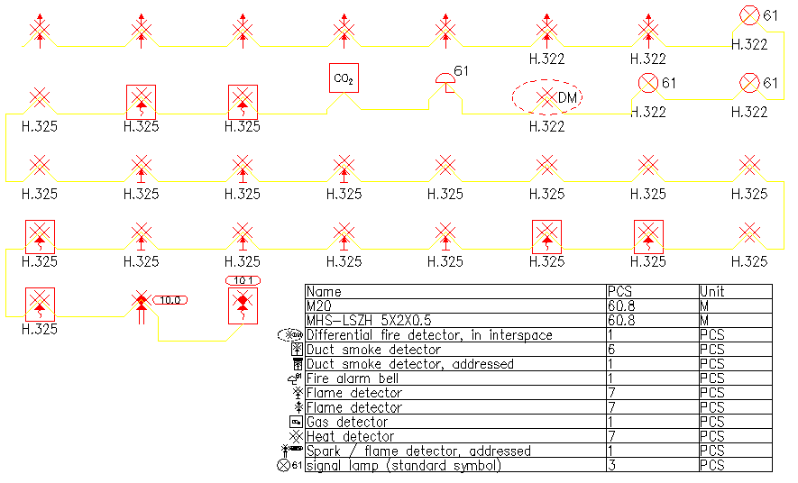
With this function, you can generate a fire detector diagram from fire detector loops in the drawing. Diagram can be generated to a layout drawing or to a drawing of its own. Quantity lists can also be created from the diagram.
-
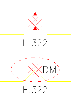
Function identifies Area boundaries and Space boundaries from the drawing. Boundary text will be seen in diagram.
-
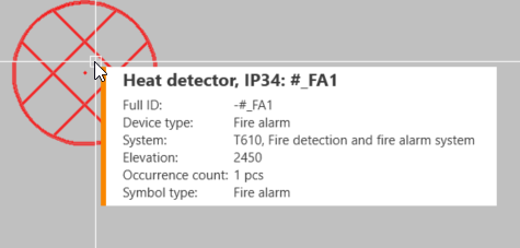
Fire detector symbol's Symbol type must be Fire alarm so that function identifies it as a fire detector. Electrical fire detector symbols have this symbol type all ready defined.
Symbol type can be seen in the information box when pointer is on top of the symbol.
-
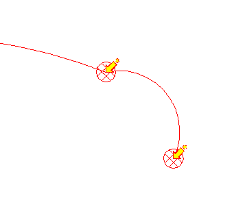
Those fire detector symbols which are already generated to diagram can be seen with yellow arrow.
Do the following:
-
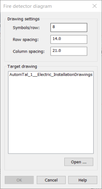
Define the drawing settings:
-
Symbols/row – Number of symbols in one row
-
Row spacing – Vertical spacing
-
Column spacing – Horizontal spacing
-
-
Select target drawing, where fire detector diagram will be drawn.
-
All the opened drawings can be selected from the dialog.
-
Target drawing can also be opened by clicking Open.
-
-
Click OK.
-
Indicate a fire detector or a fire detector wire. Fire detector wiring should be done from wiring point to wiring point with Node osnap so that diagram would be complete. (= function finds all the fire detectors in the loop).
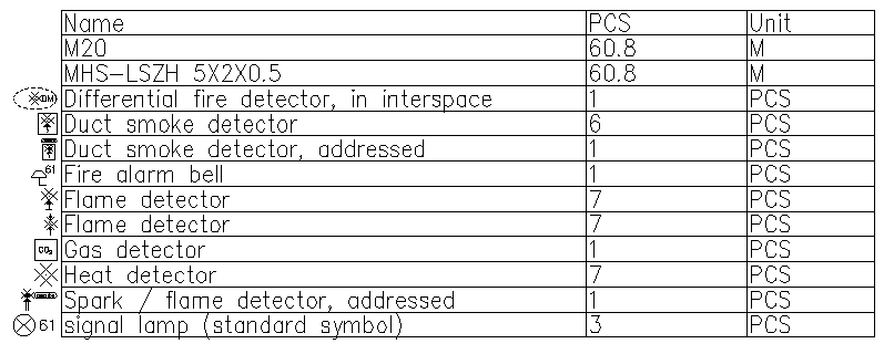
Wiring between detector have to be system information. If wiring have wiring / tube information, those will be transferred to diagram so that Quantity list can be calculated also from the diagram.
 Show/hide image
For example, Calculation functions > List functions > Count quantities from selected elements
-
Indicate the diagram starting point.