Release notes 2023
Below are the release notes for CADMATIC Electrical version 2023T1–2023T3.
The following conventions apply to these release notes:
-
Filenames, pathnames and environment variables are in italics.
-
Commands, options, dialog names, and menu choices shown in the user interface are in bold.
Cabinet Layout
New and improved features
|
Symbol standard |
A new function, Symbol standard and location, has been added to the Cabinet Layout menu. With this function you can select a new symbol standard/locale for the project. The standard determines what kind of symbol menus will open from applications. |
|
A completely new tool is available for symbol selection:
|
|
|
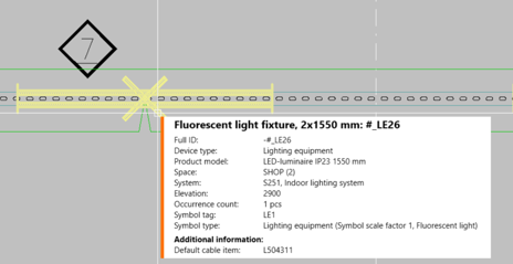
Information box |
The information box that appears when hovering over a part in the drawing has been redesigned. In addition to the appearance, a lot of attention has been paid to the readability and order of information displayed. |
|
Copying objects |
The size of the Edit values for copied objects dialog opening when copying and pasting objects can now be changed as needed. |
Bug fixes
-
The Draw cabinet function inserted cabinets with a 50 mm space between them.
-
If there was no frame in the drawing, the default drawing frame was inserted when drawing a cabinet.
Distribution Board
New and improved features
|
Symbol standard |
A new function, Symbol standard and location, has been added to the Distribution Board menu. With this function you can select a new symbol standard/locale for the project. The standard determines what kind of symbol menus will open from applications. |
|
A completely new tool is available for symbol selection:
|
|
|
Information box |
The information box that appears when hovering over a part in the drawing has been redesigned. In addition to the appearance, a lot of attention has been paid to the readability and order of information displayed. |
|
Copying objects |
The size of the Edit values for copied objects dialog opening when copying and pasting objects can now be changed as needed. |
Bug fixes
-
It was not possible to create your own symbols with the Create user symbol function.
-
Mass editing distribution board symbols resulted in two symbols for each group.
-
Power information was erased from distribution board schema rows when the drawing was not in a project.
-
Distribution board schema frame cover sheets included outdated standard information.
Layout
New and improved features
|
Symbol standard |
A new function, Symbol standard and location, has been added to the Layout menu. With this function you can select a new symbol standard/locale for the project. The standard determines what kind of symbol menus will open from applications. |
|
A completely new tool is available for symbol selection:
|
|
|
Information box |
The information box that appears when hovering over a part in the drawing has been redesigned. In addition to the appearance, a lot of attention has been paid to the readability and order of information displayed. |
|
Copying objects |
The size of the Edit values for copied objects dialog opening when copying and pasting objects can now be changed as needed. |
| Spaces |
The following changes have been done to space functions:
|
|
Cables |
It is now possible to edit cables by right-clicking them in the drawing and selecting Edit cable. |
|
The earthing symbols have been updated as follows:
|
|
|
In the Documents project tree, the right-click menu functions were different in Design mode and Print mode. The functions have now been unified. |
Bug fixes
-
When copying groups and their cables from a drawing not in a project, the cable types were changed in the copy.
-
The protective device current information was not always shown when opening the Group / feeder properties dialog for the first time.
-
The program crashed when removing a feeder with empty wiring information and selecting the Wiring option for another feeder in the same group.
-
When using the Insert symbols in area function, IDs were not assigned for symbols.
-
When inserting a device from the project tree, space information was not assigned unless the drawing was reopened or the device moved after insertion.
-
When protective device information changed, the feeder occurrences protected by that device were not updated.
-
When a symbol was assigned a position number in a drawing that was not in a project, it was no longer possible to edit the attributes.
-
When changing a symbol, attributes at a 180-degree angle were unnecessarily moved.
-
In Distribution Board and Group management, changing the order of groups/feeders did not work correctly.
-
Comparing document versions was sometimes slow.
-
There were issues with distribution board symbols: sometimes it was not possible to change the symbol (both 2D and 3D), it was allowed to assign the symbol to the location instead of the distribution board, and unintentionally created symbols were not removed.
-
When a symbol was replaced with the same symbol, the symbol scale was also reset.
-
Mass editing distribution board symbols resulted in two symbols for each group.
-
It was possible to select a location other than distribution board for a group.
-
Copying two distribution boards without wire occurrences resulted in wiring duplicates lacking either the From or To information.
-
When a column had been hidden in Distribution Board and Group management by dragging the width to zero, it stayed hidden even when restarting the dialog or using the Show columns function.
-
In the Group / feeder properties dialog, the description given to a feeder was not saved when the drawing was not in a project.
-
3D symbols changed for a product model did not update in the drawing.
-
Changing incoming feeders to outgoing feeders did not change cable's direction.
-
If the system/layer was changed after the first wiring point had already been selected, the cable went to the original layer instead of the layer of the newly selected system.
-
After synchronization, changed symbols were not always scaled correctly.
-
When wiring between storeys without group mark, the wiring direction was sometimes turned which led to removal of feeders and groups.
-
Changing a cable to a cable package broke the hierarchy between two distribution boards.
-
Some functions opened by right-clicking from the project tree caused issues.
-
Filtering made in the Distribution properties dialog also affected the Group / feeder properties dialog.
-
Exporting to IFC resulted in an error if other settings were defined before clicking Storeys.
-
When a project was copied in SQL, project check-up was not done for the cable reports.
-
There were issues with the Insert object info to drawing function: symbol texts and wiring information were only shown in functions after insertion, Text 4 was not grouped with Text 1 and Text 2 and there was no Text 3, and phasing information was missing.
-
Location texts and device texts were mixed when editing between Layout and Schematics.
Schematics
New and improved features
|
New large drawing frames are available:
In addition, a new A3 landscape frame with circuit information has been added. |
|
|
Symbol standard |
A new function, Symbol standard and location, has been added to the Schematics menu. With this function you can select a new symbol standard/locale for the project. The standard determines what kind of symbol menus will open from applications. |
|
Settings |
The following new settings have been added to the Schematics-specific settings:
|
|
The following new settings have been added to the Cable markings section in project settings:
|
|
|
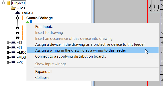
In the Wirings project tree, the following functions have been added to the right-click menu of the Cables node: |
|
|
A completely new tool is available for symbol selection:
|
|
|
Information box |
The information box that appears when hovering over a part in the drawing has been redesigned. In addition to the appearance, a lot of attention has been paid to the readability and order of information displayed. |
|
Copying objects |
The size of the Edit values for copied objects dialog opening when copying and pasting objects can now be changed as needed. |
|
The following changes have been made to the wiring functions:
|
|
|
Symbols for terminal blocks, plug connectors and device connectors have been added. They can be inserted from the Symbols menu added to the Terminal block functions toolbar. It is also possible to create your own terminal blocks via the new menus. |
Bug fixes
-
In the wiring function after indicating the first point, opening cable management or color settings caused problems.
-
When marking wiring references, the application stayed on the target sheet even when the Stay on target sheet option was not selected in the Wiring reference dialog.
-
When drawing a cable across multiple boundaries, all cables were assigned the same ID.
-
After first adding I/O channel symbols and then inserting the I/O card symbol resulted in I/O texts disappearing.
-
Reference pair IDs were not checked when adding documents to project, resulting in unwanted pairing of unpaired references.
-
When returning to the drawing from the cable edit dialog, the cable was sometimes unnecessarily saved when saving the drawing.
-
Cable type and other information was not shown correctly for cables without wires.
-
In Electrical Premium, if the user clicked the New button while drawing a cable the previously selected cable type was not taken into account for the new cable.
-
In cable combing, the cable shield was misplaced when the Pair shield setting was enabled but there was no pair shield.
-
Redrawing did not work when cables had been drawn as lines instead of polylines.
-
When changing from one project to another, the Wiring window listed cables from the previous project.
-
The Extend wire function threw an exception when extending to another document.
-
The Redraw wire function threw an exception when continuing to another document.
-
The I/O tag attribute E_IOTAGNAME[0] for channel 0 did not update.
-
Disconnecting a wiring reference sometimes resulted in an error.
-
Sometimes a terminal strip and its terminal blocks ended up in different occurrences.
-
Setting your own drawing frame as the default frame resulted in an error.
-
Changing drawing frame language sometimes resulted in duplicates.
-
Replacing a drawing frame inserted the new frame twice.
-
Location texts and device texts were mixed when editing between Layout and Schematics.
Cabinet Layout
New and improved features
|
The following changes have been made to the Symbols window:
|
|
|
Supported languages |
Polish has been added to supported languages:
|
Bug fixes
-
Starting the Draw cabinet into layout function via the project tree crashed the application.
-
When creating a product model, changing several symbols at once to user's own symbol crashed the application.
-
Deactivating or deleting 3D layers did not work.
-
When the user first closed the Symbols window and then opened a new drawing, the Symbols window was automatically reopened.
Distribution Board
New and improved features
|
The following changes have been made to the Symbols window:
|
|
|
Supported languages |
Polish has been added to supported languages:
|
Bug fixes
-
Updating a distribution board by importing new feeder data for an existing group resulted in an unwanted new feeder.
-
When the user first closed the Symbols window and then opened a new drawing, the Symbols window was automatically reopened.
-
The application suggested to change group numbering after editing a group.
Layout
New and improved features
|
The following changes have been made to the Symbols window:
|
|
|
Functions |
In addition to system and elevation, you can also use device type as a filter in the Additional information boundary function. |
|
Distribution boards and groups |
The following changes have been made in the distribution board and group functions:
|
|
Wiring |
You can now define a reference pair for a singular rise symbol. After inserting the symbol, the Select reference pair and Select reference pair from drawing functions are available in the right-click menu. |
|
Markings |
The
|
|
In storey settings, it is now possible to copy both buildings and storeys. |
|
|
Supported languages |
Polish has been added to supported languages:
|
Bug fixes
-
Removing feeders in distribution board properties sometimes resulted in an error.
-
When the application was not already running, opening a drawing with raceways sometimes resulted in an error.
-
It was not possible to generate raceways in an individual drawing if the drawing had initially been opened along with other drawings.
-
Starting wiring from an object whose system had no layer information resulted in an error.
-
If only the From and To information were defined for a cable without drawing the cable, cable length was not calculated.
-
When automatic removal was allowed wirings with feeder occurrences in distribution board schema drawings were removed, resulting in missing information.
-
Some of the project's target information was not updated to the frame.
-
After changing the distribution board symbol, it was slow to close and reopen the Distribution board properties dialog.
-
Space information sometimes disappeared if the drawing with the space boundaries and device was not also opened.
-
When counting quantities from the drawing, selecting to insert a graphical picture resulted in an error.
-
When changing a symbol, the width of an attribute (distribution board ID, for example) was sometimes unnecessarily changed.
-
In the distribution board dialog, it was possible to delete a symbol with occurrences in the drawing.
-
If the Layout-specific setting Default wiring system was not enabled, the program repeatedly asked for the system when opening the drawing.
-
New spaces were not available when counting quantities.
-
When mirroring a symbol, the symbol factor and attributes were not always correctly mirrored.
-
When the symbol was selected from the Other folder in the Symbols window, the application asked for symbol name when inserting it.
-
When the user first closed the Symbols window and then opened a new drawing, the Symbols window was automatically reopened.
-
The Remove cable function did not remove cable occurrences from the drawing.
-
Consecutive numbering was applied when copying marking symbols.
-
If filter was used when copying a symbol and left on, it was not possible to add other information for the occurrence.
-
After generating 3D, moving 2D symbols resulted in unwanted behavior for device groups. If 3D was generated again, the 3D offset also disappeared from symbols.
-
Importing lighting fixtures from DIALux resulted in an error.
Schematics
New and improved features
|
The following changes have been made to the Symbols window:
|
|
|
The following changes have been made to the wiring functions:
|
|
|
Symbol selection has been removed from the terminal block functions menu in the main toolbar. Instead, you can now easily select the desired symbol when inserting a terminal block, either from a menu or from the current drawing. |
|
|
Supported languages |
Polish has been added to supported languages:
|
Bug fixes
-
Extending a wire and then clicking Cancel in the Wiring reference dialog crashed the application.
-
Ortho set off in connection with the wiring function was not set back on after wiring.
-
Previously deleted objects were not removed from the run-time database.
-
Canceling product model creation sometimes crashed the application.
-
The application sometimes added too many symbols for I/O card product models.
-
Symbol selection resulted in an error if there were duplicate symbols whose names were the same except for the upper and lower case letters used.
-
In the Wire properties dialog, it was possible to select cable or cable package as the connection type.
-
After inserting a logic symbol via the new Symbols window, the old Logic symbols menu opened.
-
When editing symbols, it was not possible to change the color or reposition the attribute.
-
When the customer ID had been selected to be shown in the Customer IDs project settings, the internal wire number or color were not shown in wire markings despite being selected.
-
Some of the project's target information was not updated to the frame.
-
Changing the wiring color from the Draw toolbar did not work correctly.
-
If the drawing only included parts of the symbol representing multiple parts but not the actual symbol, references were not generated correctly.
-
The Symbols window did not show all symbols correctly.
-
Spare amount entered when adding a new cable or editing an existing one was not saved correctly.
-
References where sometimes lost when they were updated.
-
Right-clicking a symbol with a reference sometimes crashed the application.
-
When the user first closed the Symbols window and then opened a new drawing, the Symbols window was automatically reopened.
-
When a wire was drawn over an element and therefore automatically cut, it was shown on top of the element instead of behind it.
-
When drawing a cable through a boundary and finishing at an empty spot, the reference creation dialog did not open.
-
When merging documents, the sheet order was incorrect.
-
When first removing product information from a device in a drawing and then copying product information from another device resulted in an error.
-
In SQL Server, removing the header table object ID and saving the drawing resulted in an error.
Cabinet Layout
New and improved features
|
In project information/settings, the Standard/locale setting has been moved from the Common, symbols section to the Common section. Furthermore, Standard and Locale are now separate settings. When IEC is selected as the standard, the Locale setting is also taken into account for Finland, Estonia and Sweden:
|
|
|
A scrollbar has been added to the Electrical window, in the bottom part that shows the information for the selected item. The scrollbar appears when the selected item has so many information rows that they are not all visible. |
|
|
Information box |
When using the project tree function Show from drawing, the information box is now shown when zooming or panning. This enables viewing the object in detail while keeping its information visible. |
|
Drawings handling |
You can now save customer drawings to the same sub-directories as in the document tree with the new option Save in the directory corresponding to the project tree. For example, if the drawings are in the Schema directory in the document tree and you select to save to the drawing directory, the customer drawings will then be saved to [drawing directory]\Schema. |
Distribution Board
New and improved features
|
In project information/settings, the Standard/locale setting has been moved from the Common, symbols section to the Common section. Furthermore, Standard and Locale are now separate settings. When IEC is selected as the standard, the Locale setting is also taken into account for Finland, Estonia and Sweden:
|
|
|
A scrollbar has been added to the Electrical window, in the bottom part that shows the information for the selected item. The scrollbar appears when the selected item has so many information rows that they are not all visible. |
|
|
Information box |
When using the project tree function Show from drawing, the information box is now shown when zooming or panning. This enables viewing the object in detail while keeping its information visible. |
|
Schema drawings/sheets handling |
You can now save customer drawings to the same sub-directories as in the document tree with the new option Save in the directory corresponding to the project tree. For example, if the drawings are in the Schema directory in the document tree and you select to save to the drawing directory, the customer drawings will then be saved to [drawing directory]\Schema. |
|
Distribution board functions |
The Show group mark in Layout drawing function is now available in the right-click menu for feeders. The function opens the layout drawing in which the selected group/feeder exists. |
|
Functions |
The auxiliary functionLink graphics to Distribution Board Schema rows is now also available in the right-click menu: select the row you want to link, right-click and select the function. |
|
Symbol packages |
The |
Bug fixes
-
Opening a drawing resulted in a critical error but the drawing was still opened.
-
When opening a drawing created in an older version, some symbols disappeared.
-
Opening a drawing made with an older version resulted in an error.
-
When a drawing of type Distribution Board Schema was saved outside the project and then opened for the first time, symbol information was sometimes removed.
-
Opening a drawing including a symbol without graphics resulted in an error.
-
When importing groups from a layout drawing to a distribution board schema, the distribution board electrical position was empty.
-
Cable type was not correctly shown in distribution board documents.
-
The Create Distribution Board Schema rows to another auxiliary function did not set a default system for a new group.
-
The Swap with another group function did not work as should.
Layout
New and improved features
|
In project information/settings, the Standard/locale setting has been moved from the Common, symbols section to the Common section. Furthermore, Standard and Locale are now separate settings. When IEC is selected as the standard, the Locale setting is also taken into account for Finland, Estonia and Sweden:
|
|
|
A scrollbar has been added to the Electrical window, in the bottom part that shows the information for the selected item. The scrollbar appears when the selected item has so many information rows that they are not all visible. |
|
|
Information box |
When using the project tree function Show from drawing, the information box is now shown when zooming or panning. This enables viewing the object in detail while keeping its information visible. |
|
Symbol functions |
When a cable marking is changed with a running ID, the cable ID is changed accordingly. |
|
Functions |
The following changes have been made to the
|
|
Wiring and markings |
In the Wiring window, it is now possible to select the Running ID option. When the option has been selected, wires will be numbered consecutively. |
|
Drawing handling |
You can now save customer drawings to the same sub-directories as in the document tree with the new option Save in the directory corresponding to the project tree. For example, if the drawings are in the Schema directory in the document tree and you select to save to the drawing directory, the customer drawings will then be saved to [drawing directory]\Schema. |
|
The following changes have been made to the distribution board functions:
|
|
|
Boundaries |
You can add additional information to reference drawings with boundaries that create the additional information.
|
|
Raceways |
The 3D mode now also shows raceways in 3D instead of 2D. |
Bug fixes
-
Opening drawings with lots of content was sometimes slow or aborted.
-
Opening drawings made in earlier versions sometimes crashed the application.
-
Opening a drawing created in an older version sometimes crashed the application during the cable connection check.
-
The raceways for slight rises with alignment line were not drawn correctly.
-
Raceway T-branches were not shown correctly.
-
Connecting raceways sometimes resulted in an error.
-
Adding a drawing as a reference drawing broke the 3D raceways.
-
The second product model device occurrence did not follow device properties.
-
After using a product model related function in the Positions project tree, the position icon changed to the product model icon.
-
In Distribution board and group management, changing the column width did not work as should.
-
In Distribution Board and Group management, moving a group from one distribution board to another where the same group number already existed created a duplicate group.
-
When importing devices with = and/or + in the ID from P&ID, devices were created incorrectly.
-
It was possible to import devices from P&ID with the same ID.
-
It was not possible to add feeder information for protective devices and wirings with the Insert object info to drawing function.
-
It was possible to select the cable package type in the Insert object info to drawing function but when inserted, it was not shown.
-
When copying a cable or a cable package with cable marking, the marking system was sometimes changed for the new cable / cable package.
-
It was not possible to select a cable package as the wiring for a feeder when the drawing was not in the project.
-
In the Distribution Board properties dialog, it was not possible to select a symbol with the From drawing and File options.
-
When a protective device was disabled in the Group / feeder properties dialog, it was still left in the project tree even when automatic removal was allowed.
-
Deleting the last protective device occurrence from a drawing also deleted it from the feeder properties.
-
It was not possible to insert the access control symbol SHV0412_2 via the Symbols window.
-
Opening the Symbols window sometimes crashed the application.
-
The Mark a location ID into drawing function with the option Leader did not work when the customer ID was shown.
-
Selecting other than group symbols with the Explore the space needed for selected cables function crashed the application.
-
Editing and updating symbol's scale factors was slow.
-
When changing the mode to 2D & 3D and then back to 2D, the cable trays were left to 3D.
-
When the feeder occurrence was changed into another feeder occurrence, the wiring length was not calculated.
-
In Layout, schema drawings, the wire markings were not moved with wiring.
-
Wire references between drawings resulted in an error.
-
It was not possible to insert a distribution board to a Layout, Schema drawing if the distribution board was in another drawing of the same type.
-
The Insert symbols on element function did not prompt for size when inserting scalable light fixtures.
-
Changing distribution board ID in the Properties window resulted in additional wirings.
-
The Export groups data to manufacturers Distribution Board Schema function did not export all group data.
-
When updating missing settings for a settings file after installation, the layers were created in Finnish.
-
Element electrification did not work correctly with symbols that had 3D rotation set on Y-axis.
Schematics
New and improved features
|
In project information/settings, the Standard/locale setting has been moved from the Common, symbols section to the Common section. Furthermore, Standard and Locale are now separate settings. When IEC is selected as the standard, the Locale setting is also taken into account for Finland, Estonia and Sweden:
|
|
|
A scrollbar has been added to the Electrical window, in the bottom part that shows the information for the selected item. The scrollbar appears when the selected item has so many information rows that they are not all visible. |
|
|
Information box |
When using the project tree function Show from drawing, the information box is now shown when zooming or panning. This enables viewing the object in detail while keeping its information visible. |
|
The following functions are now available for feeders in the right-click menu:
|
|
|
Schema drawings/sheets handling |
You can now save customer drawings to the same sub-directories as in the document tree with the new option Save in the directory corresponding to the project tree. For example, if the drawings are in the Schema directory in the document tree and you select to save to the drawing directory, the customer drawings will then be saved to [drawing directory]\Schema. |
|
Symbols |
The following changes have been made to the symbol functions:
|
Bug fixes
-
When the product information setting Clear product data attributes if no product data exists was enabled, the attributes were cleared even though the drawing was not in the database.
-
In the Insert terminal block / connector dialog, the Position of ID setting did not work.
-
Using the Insert terminal block in drawing function from the Devices (location) project tree crashed the application.
-
When a cable created in the Group dialog was inserted during the same session, the cable marking was lost.
-
When importing devices with = and/or + in the ID from P&ID, devices were created incorrectly.
-
It was possible to import devices from P&ID with the same ID.
-
The Extend wiring and Extend wire functions resulted in an error.
-
When a device connector was inserted for a product model device, it was assigned the wrong symbol tag.
-
When generating circuits, attributes were not stacked.
-
Symbol menus created by the user were not available when saving symbols.
-
In some cases, unwanted wirings were created.
-
Opening the Symbols window sometimes crashed the application.
-
When generating drawings from circuits, linking an I/O index to location boundaries did not work.
-
Sometimes after clipboard import, layers were not created correctly as some elements were not handled as new.
-
The Find/replace text or attribute function did not follow the rules for replacement.
-
When redrawing a wire, the wire marking did not follow.
-
Redrawing a wire differently from the original did not affect the wire markings.
-
When drawing cables or cable packages with the Next cable automatically setting enabled, ID numbering was not continued correctly when the ID started with a number.
-
The Edit values for copied objects function did not number items correctly.
-
It was not possible to change the terminal strip connector bar ID when the terminal strip was in the main circuit.
-
When disconnecting several consecutive I/O channels via the project tree, the tree was not updated correctly.
-
When copying sheets, the device boundaries were sometimes handled before the location boundaries around them.
-
In SQL server environment, the program sometimes tried to save the symbol standard setting to the EDBUser.mdb file with the wrong project number which resulted in an error.
-
Clipboard copying between two projects sometimes resulted in an error when the copied objects included cable packages.
-
It was not possible to insert fire symbols via the Symbols window.