|
|
Single-line tab > Devices group > Boundary |
| Schematics tab > Other functions group > |
|
| Cabinet Layout tab > Devices group > |
With this function, you can define various drawing elements for a device in a drawing. There may be any elements inside the boundaries.
Do the following:
-
Enter the device ID, or select it from the tree with the
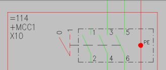
 button. If you want the device boundary ID to be written as three separate texts (object ID, electrical position and device ID) instead of the ID only, define object ID and electrical position.
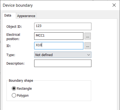
 Show/hide examples
ID only
Object ID, electrical position and ID 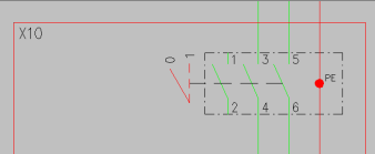
-
Select the shape for the boundary.
-
If necessary, define the appearance:
- Select the Appearance tab.
- If necessary, select boundary color and line type. By default, the color and line type come from the settings file.
- If you want to add a background symbol for the boundary, select Show symbol and define the symbol or a raster image:
- If you want to add a symbol, do the following:
- Select the Symbol option.
- If necessary, select a new color from the drop-down menu.
- If you want to scale the symbol, select the scaling method from the Scaling drop-down menu.
- Click Select symbol or the preview pane.
- Select how you want to add the symbol:
- Select from drawing – Indicate the symbol in the drawing.
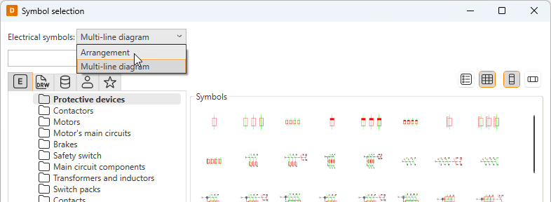
- Select from menu – Select the symbol in the Symbol selection dialog (see Symbol selection). By default, the symbols are shown based on the drawing type but you can select another drawing type (multi-line diagram or arrangement drawing) from the drop-down menu.
Click OK. The symbol you selected is now shown in the preview pane.
- If you want to add a raster image, do the following:
- Select Raster image. The Select symbol button changes to Select image.
- Click Select image and Select from disk.
- Select the desired image. The image will be scaled to fit the boundary while keeping the image aspect ratio unchanged. By default, raster images are saved to the Attachments sub-directory in the project directory.
- If you want to add a symbol, do the following:
- If you want to define a background fill color, select Boundary background color and then the desired color.
- Select whether to place the marking text inside or outside the boundary, and select the color.
- Click OK.
-
Click OK.
-
Draw the device boundary in the drawing.
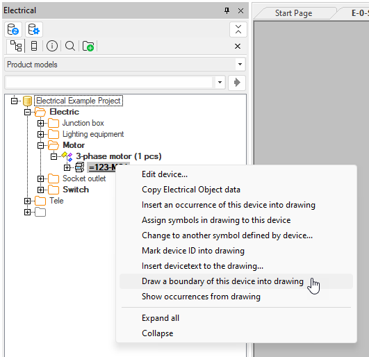
In single-line diagrams, load diagrams and multi-line diagrams, you can also draw device boundaries via the Product models project tree: right-click the desired device and select Draw a boundary of this device into drawing.
In the following image, only the device ID has been entered and it has been located inside the boundary. If the sheet object ID is, for example, =4333 and electrical position +MCC1, the full ID of the terminal block is =4333+MCC1-U100-X1:1.
If the ID X1 is not given to the terminal block, the full ID is =4333+MCC1-U100:1.
All components inside the boundary get the U100 ID. Elements on the border are included in the boundary.