|
|
Single-line tab > Cabinets and feeders group > Boundary |
| Schematics tab > Other functions group > |
|
| Cabinet Layout tab > Cabinets group > |
With this function, you can identify devices which belong to another location in the schema.
Do the following:
-
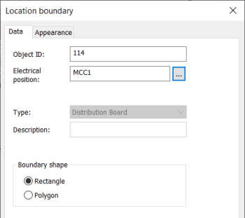
Enter Object ID, Electrical position, or both. The location boundary ID can be written in the drawing as a single ID (=123+CS1) or as two separate IDs (=123 and +CS1).
-
Select shape for the boundary.
-
If necessary, define the appearance:
- Select the Appearance tab.
- If necessary, select boundary color and line type. By default, the color and line type come from the settings file.
- If you want to add a background symbol for the boundary, select Show symbol and define the symbol or a raster image:
- If you want to add a symbol, do the following:
- Select the Symbol option.
- If necessary, select a new color from the drop-down menu.
- If you want to scale the symbol, select the scaling method from the Scaling drop-down menu.
- Click Select symbol or the preview pane.
- Select how you want to add the symbol:
- Select from drawing – Indicate the symbol in the drawing.
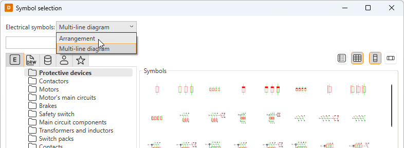
- Select from menu – Select the symbol in the Symbol selection dialog (see Symbol selection). By default, the symbols are shown based on the drawing type but you can select another drawing type (multi-line diagram or arrangement drawing) from the drop-down menu.
Click OK. The symbol you selected is now shown in the preview pane.
- If you want to add a raster image, do the following:
- Select Raster image. The Select symbol button changes to Select image.
- Click Select image and Select from disk.
- Select the desired image. The image will be scaled to fit the boundary while keeping the image aspect ratio unchanged. By default, raster images are saved to the Attachments sub-directory in the project directory.
- If you want to add a symbol, do the following:
- If you want to define a background fill color, select Boundary background color and then the desired color.
- Select whether to place the marking text inside or outside the boundary, and select the color.
- Click OK.
-
Click OK.
-
Draw the device boundary in the drawing.
With this function, you can visualize the "external" parts in the drawing and specify the parts of the different locations in the parts list.
The drawing sheet Object ID is =4333, and electrical position +MCC2. When the device data is updated after entering the device data, you can see that the switch in the following drawing has a value =4333+OK1-S2 in the device full ID of the parts list.
Creating the parts list requires that the device data is defined to device with Electrical, DB database interface. For more information, see the Manage projects and databases in DB Tool online help.