|
|
Layout tab > Cabinets and feeders group > Feeder |
| Layout tab > Cabinets and feeders group > |
With these functions, you can add and edit feeders belonging to a project.
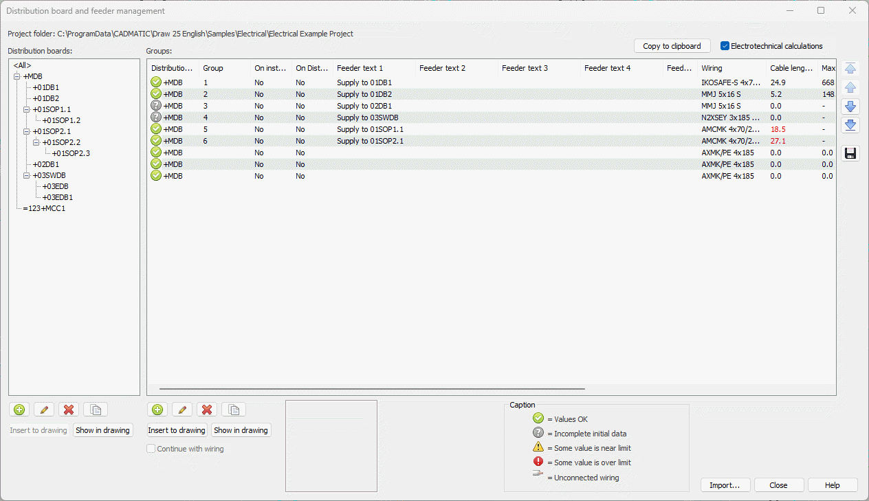
For more information on the dialog, see Manage cabinets and feeders.
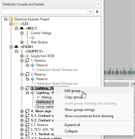
You can also start editing a group by double-clicking it in the drawing, or from the project tree by right-clicking the group and selecting Edit group.
In the New group or Group / feeder properties dialog, define the properties as follows:
-
If necessary, enter the group number. You can add a new group between existing groups so that the following group numbers will be adjusted accordingly. For example, if there already are groups 6, 7 and 8 and you add a new group 7, the old group 7 will become 8 and the old group 8 will become 9 after your confirmation.
Note: Group numbering will not be adjusted when you remove groups.
By default, the next available number is used.
 Show/hide details
When decimals (comma or point as the separator) are used in group numbering, the application suggests the next group number as follows:
-
If the previous group number was 1.1, the application suggests group number 1.2.
-
If the previous group number was 1.3, the application suggests group number 2.1.
-
When the user enters an integer (such as 2), the application suggests the next consecutive integer (such as 3).
-
If other characters (such as underscore) are used in group numbering, the number after that character is increased: after 1_1, the application suggests group number 1_2.
-
-
If necessary, select the distribution board.
-
Enter group description. The information given so far is automatically added to the Feeders section.
-
Enter feeder information below the grid.
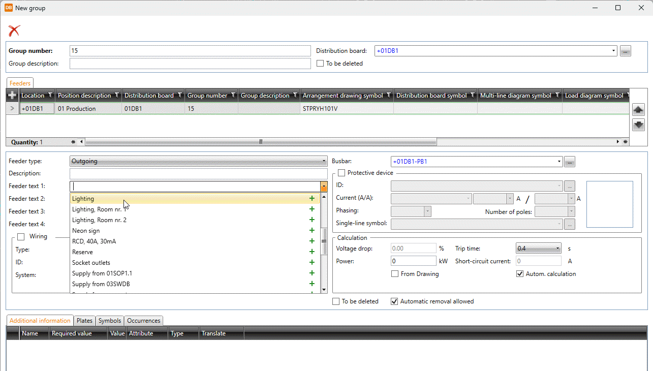
In the Feeder text fields, you can add texts to a picking list with the + buttons. The picking list items are shown at the top of the list, making selecting texts faster.
Automatic removal allowed is enabled by default. It is automatically disabled from feeders between distribution boards.
-
If necessary, select Wiring and define the information:
-
Select the wire type from the drop-down menu or by picking from the drawing. By clicking the
 button, you can select the type in cable package selection by selecting Project cable package definitions or in cable type selection by selecting Project cabletypes.
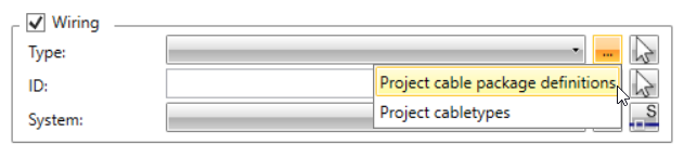
-
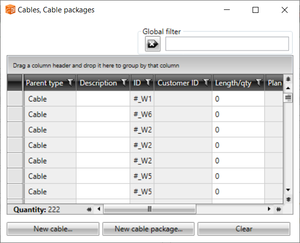
Select the ID by picking from the drawing. Alternatively, click the
button to select it in the Cables, Cable packages dialog. Via the dialog, you can also create new cables and cable packages. After selecting the ID, clicking the field opens the Cable properties dialog.
-
Select the system for wiring.
-
If necessary, select Protective device and enter the information. The values are used in calculations, and the information can be transferred to the distribution board table. Defining the protective device will create a new device.
-
Current (A/A) drop-down menu:
-
Fuse gG – The values come from the table in calculation defaults.
-
When using circuit breakers, the current is calculated according to the circuit breaker type:
-
Circuit breaker B – rated current x 5
-
Circuit breaker C – rated current x 10
-
Circuit breaker D – rated current x 20
-
Circuit breaker K – rated current x 12
-
Circuit breaker Z/A – rated current x 3
-
-
The Free text (no calculations) option allows user to enter the over-current protection as free text. However, this prevents the group to be used in electrotechnical calculations.
-
-
You can select the single-line symbol by clicking the
button and double-clicking the desired symbol in the Symbol selection dialog (see Symbol selection).
-
-
To see electrotechnical calculations, enter the power value or select From Drawing. The power is then read from symbols and electrical terminals, and the group power changes according to changes in the drawing.
-
If necessary, add more feeders with the
 button in the Feeders section and define the information as described.
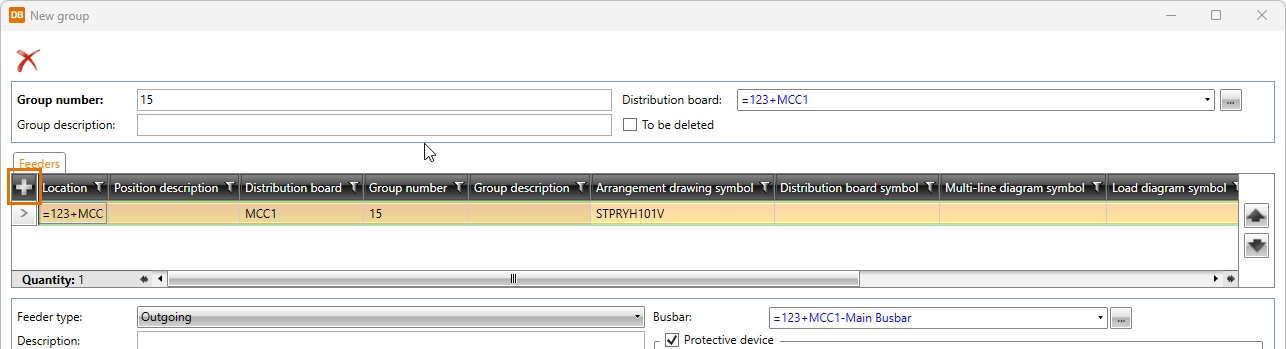
-
Edit or add additional information, plates and symbols as necessary:
-
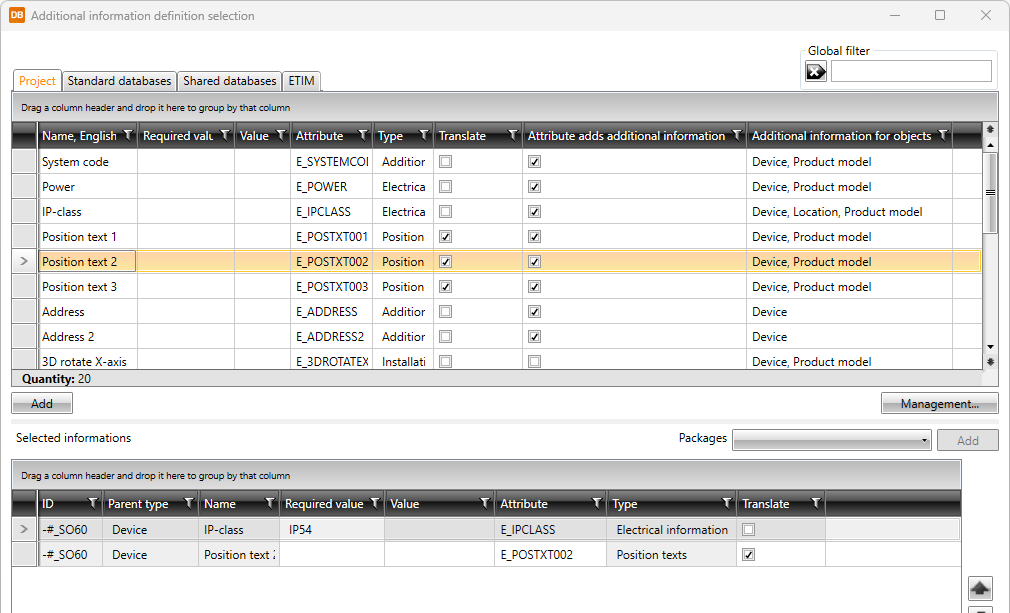
On the Additional information tab, you can select and edit additional information with the Select/Edit button.
Show/hide details
Clicking the Select/Edit button opens the Additional information definition selection dialog.
The additional information items are divided on the following tabs:
- Project – This tab shows the additional information already in the project.
- Standard databases – This tab shows the read-only database (EDBCommon.sqlite) provided with the application. It will be overwritten whenever the application is updated. You can copy additional information from this database to your own shared databases.
- Shared databases – This tab shows databases that can be shared and edited. If another user edits the data simultaneously, you can update the grid to show the changes by clicking the
 button.
 - ETIM – This tab shows ETIM (European Technical Information Model) data.
Add the desired pieces of additional information by double-clicking them or by selecting them and clicking Add.
-
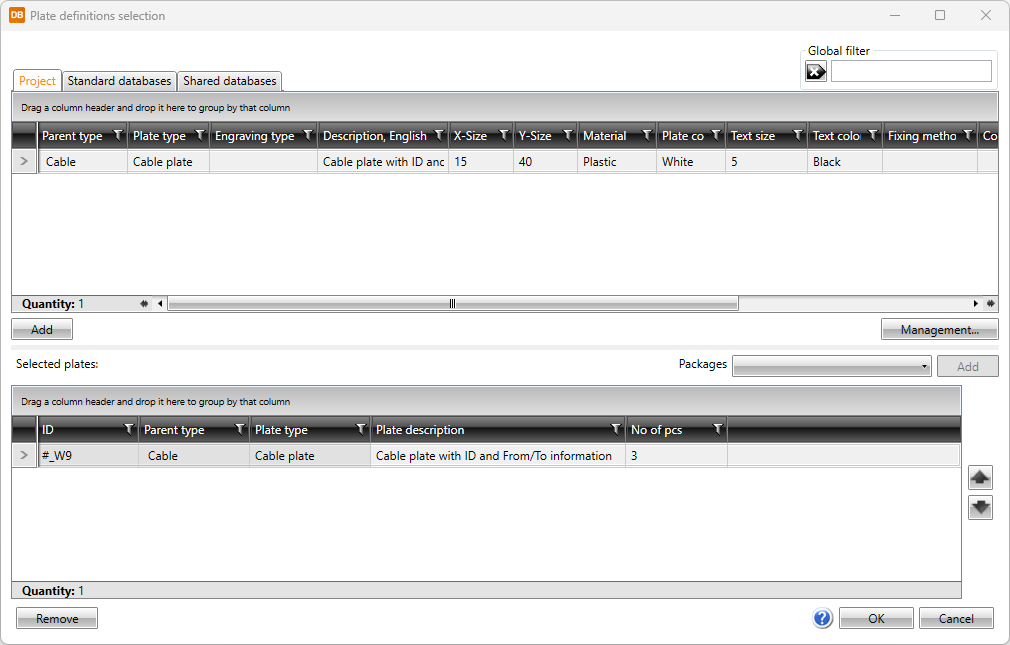
On the Plates tab, you can select and edit plates with the Select/Edit button.
Show/hide details
Clicking the Select/Edit button opens the Plate definitions selection dialog.
The plate definitions are divided on the following tabs:
- Project – This tab shows the plate definitions already in the project.
- Standard databases – This tab shows the read-only database (EDBCommon.sqlite) provided with the application.
- Shared databases – This tab shows databases that can be shared and edited. If another user edits the data simultaneously, you can update the grid to show the changes by clicking the button.
Add the desired plate definitions by double-clicking them or by selecting them and clicking Add.
-
On the Symbols tab, all the symbols in the location are shown. Overlaying symbols will cover wirings and other elements, thus improving drawing readability in some cases.
-
You can add symbols by clicking Add. After clicking Add, select whether to select the symbol from a menu, from 3D symbols, from a file, or from the drawing:
-
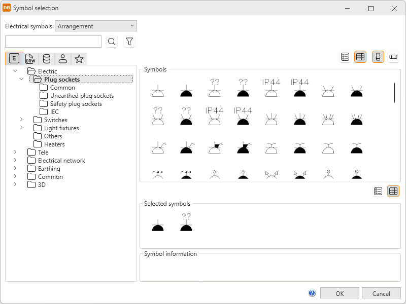
From menu – Select the desired symbol in the Symbol selection dialog.
Show/hide procedure
Do the following:
-
Select the desired tab:

Electrical symbols – This tab shows you all the Electrical symbols available. 
Symbols in current drawing – This tab shows you the symbols that have been inserted in the active drawing.

Symbols in current project – This tab shows you all the symbols in the project. 
User's symbols – This tab shows you the symbols you have saved with the Save user symbol function or imported from the user icon menus. 
Favorite symbols – This tab shows you the symbols you have defined as your favorites.
-
Double-click the symbols you want to select. Alternatively, right-click them and select Add. The symbols are moved to the selected symbols.
-
Click OK. The symbols you selected are now shown on the Symbols tab.
For more information on the Symbol selection dialog, see Symbol selection.
You can also filter the symbols more by opening and selecting the tree nodes. In the Symbols section, symbols are shown according to your selection.
-
-
3D symbol – Select the desired 3D symbols in the Symbol selection dialog by double-clicking them and clicking OK. For more information on the Symbol selection dialog, see Symbol selection.
-
From drawing – Select the desired symbol in the drawing. This option is not available in the DB tool.
-
File – Select the document type, and then the symbol. This option is not available in the DB tool.
-
-
You can replace or remove symbols that have not been inserted.
-
-
-
Click OK.
-
If you added a new group with an existing group number, the application asks whether you want to add the new group between the existing ones. Click Yes.
-
Indicate the group mark insertion point and angle.
You can also create the group to the database for later use. You can then insert the group symbol into a drawing either with the Add group function or via Distribution board and group management.