|
|
Spaces tab > Add group > Polygon space |
-
Hatch pattern: S_TILAKUVIO
-
Background color: S_TILATAYTTO
-
Boundaries of space: S_TILARAJAUS
-
Number of space: S_TILANUMEROT
-
Name of space: S_TILANIMITYKSET
-
Area of space: S_TILAALAT
With this function, you can define free-form space boundaries.
Select the corner points of the space boundary polylines one at a time. The segment data in question is defined for each segment of the boundary polyline (whether the segment is an external wall, what U-value the wall has, and so on). You can determine the segments more precisely while drawing the boundary polyline or afterward. For more information on determining the segments afterward, see Edit wall data of space objects and Add openings to space objects.
Do the following:
-
In the Space, wall dialog, select whether the wall data will be defined for the space boundary polyline to be drawn. If yes, do the following:
-
Select the wall type.
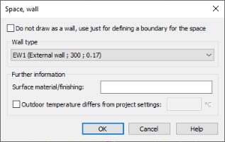
-
Enter the surface material or finishing for the wall.
-
Select whether a different outside temperature is defined for the wall (e.g. semi-heated room). If yes, enter the temperature.
You can change the wall data for each segment of the boundary polyline afterward. For more information, see Edit wall data of space objects.
-
-
Click OK.
-
Select the starting point of the space boundary polyline.
-
Select the endpoint of the first segment of the space boundary polyline.
-
Select the endpoint of the next segment of the space boundary polyline.
-
If necessary, add an opening.
 Show/hide procedure
Do the following:
-
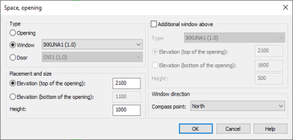
Enter opening in the command line. The Space, opening dialog opens.
-
Select a type of the opening:
-
Opening – There is no need to feed additional data for the opening.
-
Window – Do the following:
-
Select a compass point for the window.
-
Select the window type from the drop-down menu.
You can define window types in the project data.
-
-
Door – Select the door type from the list. You can define door types in the project data.
-
-
Select whether you want an additional window above the opening. If yes, do the following:
-
Select the window type from the drop-down menu.
-
Enter the elevation of the window.
-
Enter the height of the window.
-
Enter the elevation of the opening.
-
Enter the height of the opening.
-
-
Click OK.
-
-
Repeat the previous steps until you have defined all segments.
-
Press Enter to connect the first and the last point of the polyline. The Space dialog opens.
-
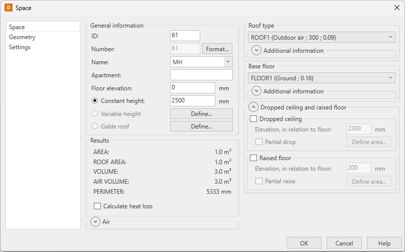
Enter the general space object data:
-
ID – The ID of the space is an individual integer for each space. The ID cannot include any other characters than numbers.
-
Number – The number is an identifier which is shown in the drawing. Click Format to define the number format. The Space number, format dialog opens.
-
Space number = ID number – The space's number is the ID number. You cannot add any other characters to the number.
-
Formatted space number including ID number – Define a format of the number. Enter [ID] as the value, because the space number must include the ID number.
-
Space number as a free text – Define a number of your choosing for the space object.
Keep in mind that entering the number as a free text excludes the space from certain automatic functions, such as renumbering the spaces when copying them. You have to correct the number by hand every time.
-
-
Name – Space names are recorded in the file HUONETUN.TXT. You can add your own space identifiers by opening the file in a text editor (e.g. Windows Notepad editor), if needed.
-
Apartment
-
Floor elevation
-
-
Select the determination type of the space height:
-
Constant height – Enter the space height in millimeters, and click Set to update the data for the space.
-
Variable height – You have to have three-point height data of the room. Click Define. Select the first known point, and enter the point's elevation. Repeat for all three points.
-
Gable roof – You have to have four-point height data of the room. Click Define. Select the first known point, and enter the point's elevation. Repeat for all four points.
The program determines a plane that forms a "ceiling" for the rooms.
-
-
Select the roof structure, and enter other information:
-
If the type of the roof is Intermediate floor, select whether different temperature is used in the space above it. If yes, enter the temperature.
-
Enter the surface material or finishing of the roof.
-
For Area differs from space area, select whether the real roof area is different from the defined roof area, such as an inclined roof. If yes, enter the area of the roof.
-
If the space has skylights, select Skylights. Enter the total area of the skylights into the field, and select the skylight type from the drop-down menu.
-
-
Select base floor structure, and enter other information:
-
If the type of the base floor is Intermediate floor, select whether different temperature is used in the space below. If yes, enter the temperature.
-
Enter the surface material or finishing for the base floor.
-
For Area differs from space area, select whether the base floor area is different from the defined space area. If yes, enter the area of the base floor.
-
-
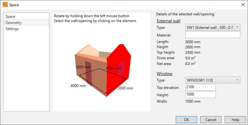
Edit the walls and openings of the space on the Geometry tab:
-
Click Geometry.
-
Select a wall from the picture.
-
The information of the selected wall is displayed on the right and e.g. the size or height of the window can be modified.
-
-
Define the style for the space:
-
Select Settings.
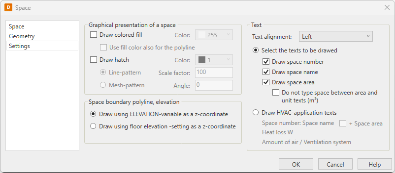
-
Select whether a background fill is drawn into the space.
If yes, do the following:
-
Select a fill color from the drop-down menu.
-
Select whether the space boundary polyline is drawn with the fill color.
-
-
Select whether a background hatch pattern is drawn into the space.
If yes, do the following:
-
Select a color from the drop-down menu.
-
Select the background pattern type (line pattern or mesh pattern).
-
Enter the pattern size factor, which is the distance between the drawn lines.
-
Enter the hatch pattern angle.
-
-
Select Draw using ELEVATION-variable as a z-coordinate. The ELEVATION variable defines a elevation (z axis) which is used while drawing. Generally, ELEVATION should be 0 when drawing floor plans.
- Select the text align method.
-
Select a text format for the space:
-
Select whether the space number is drawn.
-
Select whether the space name is drawn.
-
Select whether the space area is drawn.
If yes, select whether the space between the area and the unit is left out or not.
-
-
-
Click OK to save the space data.
-
Indicate where to insert the space data in the drawing.