Layout tab > 3D and view group > ![]() 3D functions menu > Collision checking
3D functions menu > Collision checking
With collision checking it's possible to detect a collision between cableway and other elements, such as pipes and other cableways.
The collision checking function adds arrows to the drawing. you can remove the arrows with the Delete arrows from collision checking function.
Create and update collision geometry
Layout tab > 3D and view group > ![]() 3D functions menu > Collision checking > Create collision geometry
3D functions menu > Collision checking > Create collision geometry
Layout tab > 3D and view group > ![]() 3D functions menu > Collision checking > Update collision geometry
3D functions menu > Collision checking > Update collision geometry
Electrical cableways hold collision data by default. For other 3D objects, it is necessary to create a separate collision geometry to detect collisions between cableways and other objects. Creation of collision geometry also enables picking of elevation also from reference drawings, such as imported IFC files. This eases for example drawing cableways above or below crossing elements.
Note: Collision geometry will not be saved to the drawing; it will only be available while the drawing is open. Before the next collision check, the geometry needs to be generated again.
The application needs data of objects in the 3D space for collision detection. The collision geometry enables real time detection between 3D objects.
- Tolerance – Distance how much elements can cross each other that will be interpreted as collision. Tolerance can also be negative, when for example tolerance of -10 mm would declare collision between two elements that pass each other from distance less than 10 mm.
- Selection – Collision checking can be performed from all elements in drawing or just selected elements. Collision geometry will still be generated for all elements but collisions will be displayed only for selected elements.
- Observed reference drawings – Collision geometry can also be generated for reference drawings.
- Observed elements – Determines which type of elements collision checking will be executed. For example you can include all pipes imported from IFC-file by including symbols that has IfcType attribute with value beginning with Duct: Attribute IfcType, Value: Duct*.

Clicking OK starts the creation of collision geometry with the current settings.
With the Update collision geometry function, you can recreate collision geometry using previous settings.
The Collision checking of 3D parts function always creates collision geometry before checking for collisions.
You can define 3D collision detection settings when drawing or editing a cableway: click the ![]() button in the Geometry section to open the Advanced settings dialog. In these settings, you
can find
the 3D-collision detection section:
button in the Geometry section to open the Advanced settings dialog. In these settings, you
can find
the 3D-collision detection section:
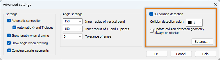
If you select Update collision detection geometry always on startup, the geometry will be created every time you use the cableway function.
With Settings, you can launch Collision manager. Clicking OK in Collision manager starts the creation of collision geometry with the current settings.
Check collision for 3D parts
Layout tab > 3D and view group > ![]() 3D functions menu > Collision checking > Collision checking of 3D parts
3D functions menu > Collision checking > Collision checking of 3D parts
With this function, you can inspect 3D objects and search for collisions according to the collision settings. For Electrical cableways, the collision checking is automated but for other drawings you need to separately create the collision inspection geometry.
Collision checking detects collisions between 3D objects (3D surface, 3D mesh) according to the collision settings. Collisions can also be detected from reference drawings.
Collision checking marks collisions with arrows. After correction, the arrows can be removed one by one or all at once with Delete arrows from collision checking.
Realtime collision checking
When drawing a cableway that collides with other objects according to the tolerance defined in the collision settings, the colliding part is highlighted.
Note: The highlight color is not shown, if the Display colors by layers setting is activated. To show the highlight color, select Layer > Display colors by objects from the main menu.
Tip: Collision checking also works for reference drawings that have been disabled after creating the collision geometry. Therefore, you can hide the 3D reference drawing and show the 2D pipe drawing, for example, while drawing cableways.