Insert contacts
Let's insert contacts according to the example drawing. The cross-references for the auxiliary contact pack and the contact are automatically added.
Do the following:
-
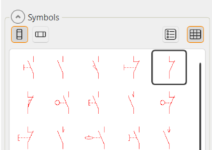
In the Symbols window, select Contacts and insert the contact symbol:
-
Insert the symbol into the drawing.
-
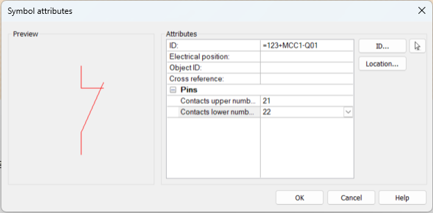
Define the following:
-
ID – From the drop-down menu, select =123+MCC1-Q01.
The =123+MCC1 part will be removed when the symbol is inserted because the same information is included in the drawing frame.
-
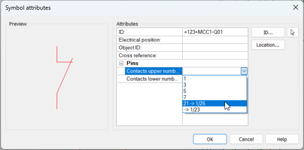
Contacts upper number – From the drop-down menu, select 21 (available after the auxiliary contact pack has been inserted).
-
Contacts lower number – From the drop-down menu, select 22 (available after the auxiliary contact pack has been inserted).
When inserting the next contact, you can see the contacts already inserted: 1/25 = sheet 1, wiring reference pair 25:
-
-
Insert the other contacts.
Tip: You can find the desired symbols quickly by entering the full symbol name in the symbol selection window search field.
-
Opening contact 21/22 for contactor Q02, symbol name Normally-closed contact
-
Contactor 1/2 for the circuit breaker F10, symbol name Circuit breaker
-
Normally-open contact 13/14 for the motor protection switch Q11, symbol name Normally-open contact
-
Normally-open contact 13/14 for the safety switch Q10, symbol name Normally-open contact
Note: The ID is left empty as it will be taken from the device boundary =123-Q10.
-
Contact 19/20 for motor's thermal protector F1, symbol name Thermal protector, normally-closed contact
 Previous Previous |
Next

|