Create and edit groups and feeders
|
|
Single-line tab > Cabinets and feeders group > Feeder |
| Single-line tab > Cabinets and feeders group > |
|
| Schematics tab > Other functions group > |
|
| Schematics tab > Other functions group > |
You can create groups of cables and protective devices, and edit them.
Create feeders
Do the following:
-
Select the Create group/feeder function.
-
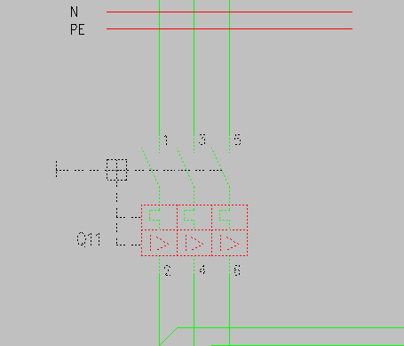
Select the elements (such as a motor protective device) of which you want to create a group.
-
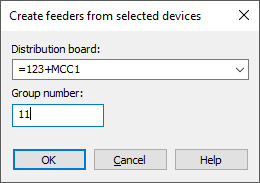
Press Enter. The Create feeders from selected devices or Create feeders from selected cables dialog opens.
-
From the Distribution board drop-down menu, select the desired distribution board.
-
In the Group number field, enter the desired group number.
-
Click OK. The group is now available in the project tree.
Edit feeders
Do the following:
-
Select the Edit group/feeder function.
-
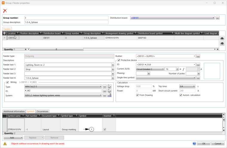
Select a protective device, or a cable. The Group / feeder properties dialog opens.
-
Edit the group details, such as the description, as necessary.
-
Enter feeder information below the grid.
You can also add some information via the grid by double-clicking the cells. Both in the grid and the Feeder text fields you can add texts to a picking list with the + buttons. The picking list is shown at the top of the list, and makes selecting texts faster.
-
If necessary, select Wiring and define the information:
-
Select the wire type from the drop-down menu or by picking from the drawing. By clicking the
 button, you can select the type in cable package selection by selecting Project cable package definitions or in cable type selection by selecting Project cabletypes.
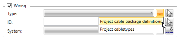
-
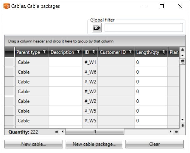
Select the ID by picking from the drawing. Alternatively, click the
button to select it in the Cables, Cable packages dialog. Via the dialog, you can also create new cables and cable packages. After selecting the ID, clicking the field opens the Cable properties dialog.
-
Select the system for wiring.
-
If necessary, select Protective device and enter the information.
You can select a symbol for the protective device from the Single-line symbol drop-down menu that shows all single-line protective device symbols in the project.
-
If the desired symbol is not available in the drop-down menu, you can select it from the Fuses, Circuit breakers or Protection switches menu by clicking the
button. -
The number of poles is automatically taken from the symbol definition, if one exists.
-
If the symbol has been inserted, it cannot be changed.
-
-
To see electrotechnical calculations, enter the power value or select From Drawing. The power is then read from symbols and electrical terminals, and the group power changes according to changes in the drawing.
-
If necessary, add more feeders with the
 button in the Feeders section and define the information as described.
 -
Edit or add additional information, plates and symbols as necessary:
-
On the Additional information tab, you can select and edit additional information with the Select/Edit button.
-
On the Plates tab, you can select and edit plates with the Select/Edit button.
-
On the Symbols tab, all the symbols in the location are shown. You can select symbols by clicking Select, and remove them by clicking Remove.
-
-
Click OK.