Block Properties
Tools > More Settings > Block Properties

The Block Properties dialog consists of seven tabs each containing different types of block property options that you can modify, as follows:
- Area and Description – Set the block area measurement and description.
- Solid/Dash – Set how blocks are presented in the graphical window.
- Text Properties – Set the values regarding the representation of each type of text in different scales.
- Part Symbol – Set whether part symbols appear automatically on created plates or not.
- Shape Line – Change the pen numbers and dash types for all the different types of hull shape lines.
- Visibility – Set the visibility values of construction parts in different views for the active block.
- Update – Set the behavior of the default Update Drawing function.
The block properties are only available with full access when the block is checked out.
Click Apply to save and apply changes within the active tab and keep the dialog open.
Click OK to save and apply changes in all tabs, and close the dialog.
In COS projects, the changes are applied at other sites only when the block is saved and downloaded after replication.
Area and Description
To insert or modify the area measurements, give the minimum and the maximum value for Length, Breadth, and Height of the active block area.
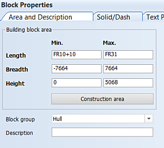
Building block area – Set the minimum and maximum values for length, breadth, and height of the active block area.
Construction area – Inserts the default values of the construction block area, based on the construction currently present in the block.
Note: Using a width grid whose direction is towards the port side is not reflected in the presentation of the breadth (width) values here. The system always shows the minimum (port side) values as negative and the maximum (starboard) values as positive. Positive minimum values and negative maximum values can be entered in the input boxes for breadth if the width grid runs towards the port side, but when the settings are opened again, the minimum values are shown as negative, and maximum values as positive.
Block group – Set the block group which the active block will be belong to.
Description – Set a description for the active block.
Solid/Dash
Select a block or block group, and click Drawn, Dashed, or Off to set the blocks to be drawn using a solid or a dashed line, or to not be visible. In general, only the block that is being worked on should be presented as drawn. The other blocks around it can be presented dashed, if it is necessary to see them as well.
You can also use the check boxes to define the settings. For example, you can select a block group, and make all the blocks to have the same setting, and then set individual blocks differently by using the check boxes.
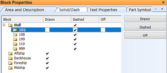
- Drawn – The block is drawn with a solid line.
- Dashed – The block is drawn with a dashed line.
- Off – The block is not drawn.
Note: In HiLTop, only the reference surfaces block group, and the blocks belonging to it, is shown. You can set a block group as reference surface group in System Management > Projects > Block Groups. In all the other applications than HiLTop, all block groups, also block groups with no blocks, are shown.
Text Properties
The item groups for which text properties can be set are shown at the top part of the dialog.
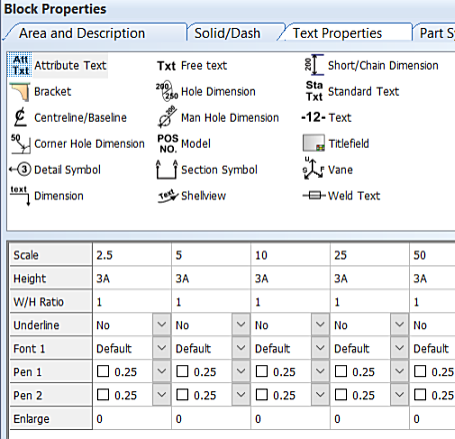
Each item group has its own set of properties. The properties of the selected item group are displayed in the property table at the lower part of the dialog.
Text properties are set separately for each drawing scale. The columns of the table are ordered by the drawing scale. Each column contains the properties specific to one specific scale.
Select an item group, and make the desired changes to the properties. Repeat for as many item groups as needed. For detailed information on the item groups and the property settings, see Item Groups for Text Properties and Text Property Settings.
Clicking Default restores the default values for the selected item group (for the active block). The default values are defined in System Management > Presentation > Text/Dimension > Text Properties.
Click OK to save the changes and close the dialog, or Apply to save the changes and keep the dialog open.
Part Symbol
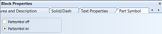
Select Partsymbol on to have part symbols appear automatically on created plates.
Select Partsymbol off to have part symbols not appear automatically.
Shape Line
There are two presentation categories for each hull shape line type: Solid and Dashed. You can set the pen and dash numbers that the block will use for representing each type of hull shape line.
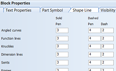
Solid – The values in this category apply to hull lines presented with solid lines.
- Pen – Sets the pen colour for each hull line type.
Dashed – The values in this category apply to hull lines presented with dashed lines.
- Pen – Sets the pen colour for each hull line type.
- Dash – Sets the type of dash pattern for each hull line type.
Default – Set all values back to their defaults.
Visibility
Change the visibility, such the viewing distance, for various construction items in different views.
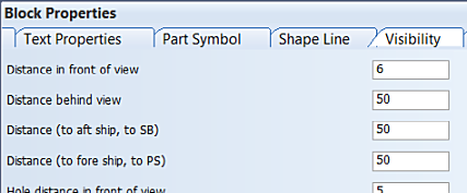
The default values are set in System Management > Presentation > Visibility.
See also Views and drawings.
Update

Active block / All blocks – Set whether the active block only, or all solid and/or dashed blocks are refreshed by default when updating a drawing with the Update Drawing function.
Update automatically placed dimensions – Select this to also refresh automatically placed dimensions when a drawing is updated.
- Automatically placed dimensions are updated according to the rules defined in the Auto Dimension function.
- Selecting this setting also makes the rule based dimensions to be automatically generated by default when creating new views and/or recalculating existing views.