Exporting to OCX XML
Export Hull construction to OCX (Open Class 3D Exchange) XML format. You can export one or several blocks.
Consider the following:
-
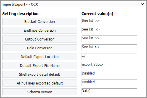
Conversion settings for brackets, profile end types, cutouts and holes are needed for the export. The system handles conversions of other structural entities automatically. These settings define how CADMATIC Hull structural entities are translated into OCX XML format. Default settings are included in the default norms. The settings can be viewed and modified in System Management > Import/Export > OCX. See OCX.
-
Construction is always exported. If a user-defined conversion setting does not exist for a construction item type, the system will use its default conversion. In such a case the export will contain a definition for a default construction part instead of the actual part.
-
There is a difference in the exported data between Hull and OCX. In Hull the moulded side is used when defining plate data, that is, the plane of the plate refers to the plane that coincides with the moulded side of the plate. However, in OCX the plane of a plate is the plane that is in the centre of the plate.
-
When exporting the plates, the plate area needs to be part of the logistical record layout.
-
The Hull project's grid definitions (defined in Grid Manager) are included in the CoordinateSystem element in the export. All grids are exported as collections under it from schema 3.0.0 onwards. See also the setting Schema version in OCX.
-
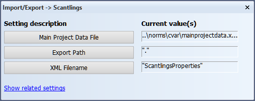
Material information must be defined in the Main Project Data File, which is by default an Excel file in the project norms <project>\norms\cvar\mainprojectdata.xlsx. This configuration must exist, because the Scantlings configuration menu contains the setting for the location of the mainprojectdata file. In this file, Hull material codes are mapped to material types, and material properties are defined. The file is shared with the Export to Mars2000 function. See Material mapping and properties for more information.
Note: The configuration file must exist in the path provided in the Scantlings configuration.
-
A configuration file for the regular scantlings export must be created. This can be done by either adding a filled in scantlings.conf to the project norms (<project>\norms\cvar\scantlings.conf) or by editing the file in System Management > Import/Export > Scantlings for the first time upon which it will be generated. See Scantlings for more information.
-
The defaults for the location and name of the exported file can be changed in the Import/Export > OCX dialog. A default export path can be set with the Default Export Location setting. A default export file name can be set with the Default Export File Name setting. Both of these are then changed by clicking the Set Default button within their respective dialogs. When exporting, the export will always default to this combination of path and file name.
Note: Plate relations containing arcs are exported as free edges.
Note: A single face plate that is attached to multiple plates is only exported as a single face plate if there are no gaps between the plates. There must be a continuous contour where the face plate runs along the plate edges, or the face plate will be exported as multiple face plates, one for each plate.
Do the following:
-
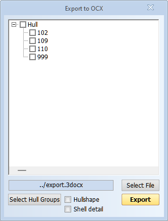
Select Hull > Export > Scantlings > OCX in the 3D-Contek application. The Export to OCX dialog opens.
-
Select the blocks to export. You can select multiple blocks.
-
Click Select File. The Windows Save As dialog opens. Browse to the export file location. You can change the file name in the Save As dialog as desired.
-
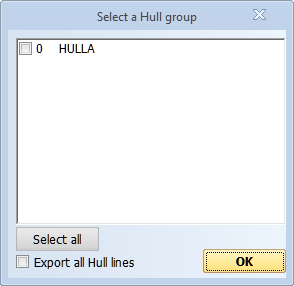
Select Hullshape to only export hull group 0 (hull shape). If you want to include other hull groups in the export, such as reference surfaces, click Select Hull Groups. The Select a Hull group dialog opens. Select the hull groups to include in the export.
Note: By default, only those hull lines which are used as boundaries for shell plates are exported. To include all hull lines in the export, select the Export all hull lines option in the Select a Hull group dialog. Exporting all hull lines can also enabled by default in System Management > Import/Export > OCX > All hull lines exported default
-
Select Shell detail to include detailed topological information from relations to the hull line in the export.
Note: This setting is incompatible with schema versions from 3.0.0 onwards.
-
Click Export to start the export.
The system writes a log file of the export, and stores it in the Windows temp folder (exportToOcx_<timestamp>.log). The log contains a summary of the errors and warnings that occurred during the export process. The log shows which construction item types are missing valid conversion settings. The log is also shown in the Message Window at the lower part of the graphical window.